This chapter discusses air sealing and insulating attics and roofs. Whether the thermal boundary is at the attic floor or the roof, the air barrier and the insulation should be adjacent to one another and continuous at that location.
4.1 Air-Sealing Attics and Roofs
Air sealing attics and roofs may be the most important and cost effective weatherization measure and one of the most challenging. The attic or roof is a prominent location for air-leakage and moisture damage. Building fires tend to spread through large air leaks in the attic. Air-sealing can prevent these problems.
4.1.1 Sealing around Manufactured Chimneys
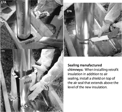
Several types of manufactured chimneys are common in residential buildings. We explain these in “Manufactured Chimneys” on page 301. Observe the required clearances listed in “Clearances to Combustibles for Common Chimneys” on page 300. Install the chimney’s air seal with an insulation shield if you’ll retrofit insulation after air sealing.
ü Remove existing insulation from around the manufactured chimney.
ü Cut light gauge aluminum or galvanized steel in two pieces with half-circle holes for the chimney that create small caulk-able cracks.
ü Bed the metal in sealant and staple, nail, or screw the metal in place.
ü Caulk around the junction of the chimney and the metal air seal with non-combustible caulk labeled ASTM E136.
ü Cut and assemble a metal insulation shield that creates a 3-inch space between the shield and chimney and extends above the planned level of the retrofit insulation.
ü Move the existing insulation that you removed back into place around the insulation shield before installing the retrofit insulation.

4.1.2 Sealing around Fireplaces and Chimneys
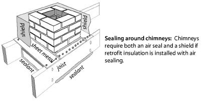
Leaks around fireplace chimneys are often severe air leaks. Use this procedure to seal air leaks through the chimney chase.
ü Cut sheet metal to fit the gap that borders the chimney with overlaps connecting to nearby attic framing lumber.
ü Bed the sheet metal air seal in sealant, and then fasten the sheet metal to the attic framing with staples, nails, or screws.
ü Seal the metal patch to chimney or flue with a non-combustible sealant labeled ASTM E136.
ü Seal other gaps between the attic and the chimney chase.
ü For large chimney chases, cover the chase opening with structural material such as plywood. Maintain clearances between the structural seal and the metal or masonry chimney as listed in “Clearances to Combustibles for Common Chimneys” on page 300.
4.1.3 Air Sealing Recessed Lights
|
SWS Details: 3.1003.5 Dropped Ceiling with Light Boxes and Fixtures, 3.1003.6 Dropped Soffits, 4.1001.1 Non-Insulation Contact (IC) Recessed Light |
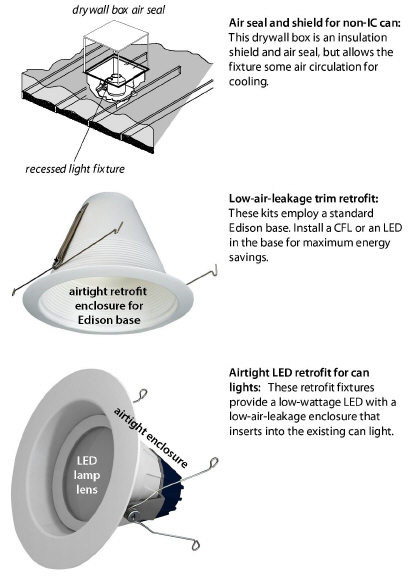
The most common type of recessed light fixture is the round can. However all recessed light fixtures are potential air leaks and air-leakage conduits. Many recessed light fixtures have safety switches that turn them off at around 150° F. Too much insulation covering the fixture or foam insulation could cause the safety switch to cycle.
Types of Recessed Can Lights
There are three kinds of recessed can lights found in buildings with regard to their need for insulation shielding. (IC means insulation contact. AT means airtight.)
1. Older cans that aren’t rated for contact with insulation, known as non-IC-rated cans.
2. IC-rated cans that may be covered with fibrous insulation but not foam insulation.
3. ICAT-rated cans that are airtight in addition to being rated for insulation contact.
Options for Sealing Non-IC-Rated Fixtures
Consider these three options for air sealing recessed can lights. You can enclose the existing fixture, replace it with an ICAT recessed fixture, or retrofit it with an LED retrofit kit.
1. Build a Class I fire-resistant enclosure over the non-IC-rated fixture leaving at least 3 inches clearance from insulation on all sides and to the lid of the enclosure. Seal this enclosure to surrounding materials with foam to create an airtight assembly. The top of this fire-resistant enclosure must have an R-value of 0.5 or less. Don’t cover the top of the enclosure with insulation.
2. Replace the recessed fixture with a new ICAT fixture, and carefully seal around this airtight fixture.
3. Install an airtight LED-retrofit assembly in the existing can. This option assures that the light is energy-efficient and low heat because you replace the existing incandescent lamp holder with a cooler LED retrofit assembly.
If the non-IC rated fixture remains, replace the incandescent lamp with a compact fluorescent lamp (CFLs) or LED lamp, which operates cool and minimizes the fire hazard associated with these fixtures.
Caution: Don’t cover IC-rated or airtight IC-rated fixtures with spray foam insulation. The foam’s high R-value and continuous contact could overheat the fixture.
See also "Safety Preparations for Attic Insulation" on page 131.
4.1.4 Sealing Stairways to Unconditioned Attics
|
SWS Details: 3.1002.1 Interior with Sloped Ceiling, 3.1002.2 Stairwell to Attic—Door at Bottom with No Ceiling Above, 3.1002.3 Stairwell to Attic—Door at Top with Finished Ceiling Above |
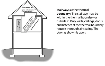
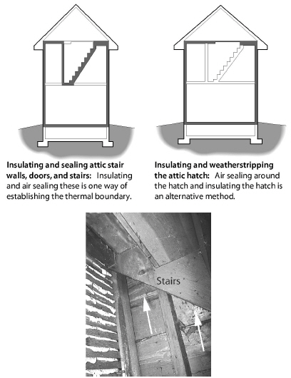
There are a variety of stairways and hatchways that provide access from the building to an unconditioned attic.
The following components of these stairways may need air sealing and insulation depending on whether they are at the thermal boundary.
• The risers and treads of the stairways
• The surrounding triangular walls
• Vertical or horizontal doors or hatches
• The framing and sheeting surrounding the doors or hatches
• Sloping ceilings above the stairways
Consider the following air-sealing measures.
ü Study the geometry of the stairway and decide where to establish the air barrier and install the insulation.
ü Weatherstrip around doors and hatches if the door or hatch is at the thermal boundary.
ü Seal the walls, stair-stringer space, and ceiling if they are at the thermal boundary.
ü Seal gaps between the door frame and the framing with one-part foam, two-part foam, or caulking.
ü If attic insulation is or will be above the level of the attic-access hole, build a dam that extends above the top of the floor joists around attic access hatch. Make the dam strong enough to support the weight of anyone entering the attic. Air seal this dam to the surrounding structure of the attic access hatch.
ü With existing insulation dams, clear existing fibrous insulation from around dam around the hatch framing. Spray two-part foam around the perimeter to reduce heat loss through the hatch framing.
See also "Walk-Up Stairways and Doors" on page 151.
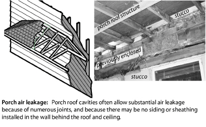
4.1.5 Sealing Porch Roof Structures
Porch roofs on older homes were often built at the framing stage or before the water resistive barrier (WRB) and siding were installed. The porch’s roof sheathing, roofing, and tongue-and-groove ceiling aren’t air barriers. The loosely fitting wall sheathing or unsheathed wall allows air into the wall cavities where it migrates into the conditioned space or convects heat into or out of the building.
Consider these options for air sealing leakage through a porch roof.
• Remove part of the porch ceiling and install a rigid air barrier or cover the area with closed-cell spray foam.
• Dense-pack the porch-roof cavity to reduce the airflow through the porch roof and wall cavities.
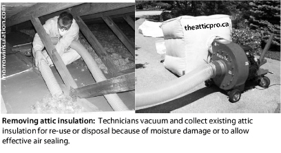
4.1.6 Removing Insulation for Attic Air Sealing
Attic air sealing is essential for successful air sealing jobs. Removing insulation from an attic for the purpose of air sealing may be worth the cost and effort. Batts and blankets can be rolled up, moved out of the way, and re-used. Loose fill insulation can be vacuumed with commercial vacuum machines available from the same suppliers that sell insulation-blowing machines. Many insulation companies own large vacuums for loose-fill insulation.
4.1.7 Sealing Joist Cavities Under Knee Walls
|
SWS Detail: 4.1004.1 Preparation for Dense Packing, 4.1004.2 Preparation for Batt Insulation |
Floor joist cavities beneath knee walls allow air from a ventilated attic space to enter the floor cavity between stories. This is a problem of homes with a finished attic, also known as story-and-a-half homes.
Connect the knee wall with the ceiling of the space below by creating a rigid seal under the knee wall. Use a combination of rigid foam with one-part or two-part foam sealing the perimeter. Or, use fiberglass batt with spray two-part foam as a strong airtight seal covering over the fiberglass batt.
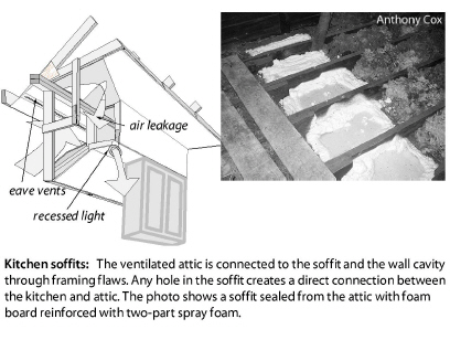
4.1.8 Sealing Kitchen or Bathroom Interior Soffits
|
SWS Detail: 3.1001.1 Penetrations and Chases, 3.1001.2 Chase Capping, 3.1003.6 Dropped Soffits |
Many modern homes have soffits above kitchen cabinets and in bathrooms. Large rectangular passages link the attic with the soffit cavity. At best, the air convects heat into or out of the conditioned space. At worst, attic air infiltrates the conditioned space through openings in the soffit or associated framing.
ü Seal the soffit with plywood or drywall, bedded in sealant and fastened to ceiling joists and soffit framing with screws, nails or staples.
ü Seal the patch’s perimeter thoroughly with two-part foam or caulking.
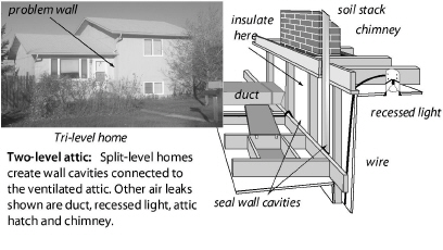
4.1.9 Sealing Two-Level Attics
|
SWS Detail: 3.1001.3 Walls Open to Attic—Balloon Framing and Double Walls |
Split-level and tri-level homes have a particular air leakage problem related to the walls and stairways dividing the homes’ levels.
ü Seal wall cavities below the ceiling joists from the attic with a rigid material fastened to studs and wall material.
ü Or insert folded fiberglass batt into the wall cavity and spray with at least one inch of two-part foam to create a rigid air seal.
ü Dense-pack the transitional wall or insulate it with fiberglass batts. Either way install an air barrier on the attic side of the wall.
ü Seal all penetrations between both attics and conditioned areas.
4.1.10 Sealing Suspended Ceilings
Suspended ceilings are seldom airtight, especially the T-bar variety. T-bar ceilings and other non-structural suspended ceilings may not be a practical location to establish an air barrier.
• The ceiling was installed room by room.
• The amount of spray foam necessary to seal the joints may be too heavy for the non-structural suspended ceiling to support.
• Technicians may need access to the crawl space above the suspended ceiling in multiple locations to work on utilities installed above the ceiling.
Take down some panels of a suspended ceiling to inspect the suspended ceiling or gain access from above. Observe these options for air-sealing non-structural suspended ceilings.
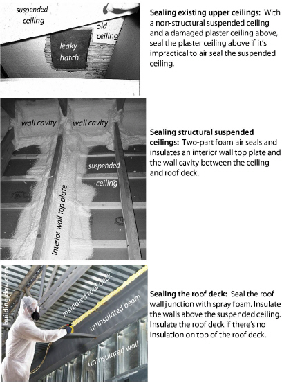
• A plaster ceiling above a non-structural suspended ceiling is weak and failing. You plan to install insulation on top of existing insulation above the failing ceiling. Reinforce the existing plaster with screws and plaster washers. Screw drywall over areas of missing plaster. Seal the joints and perimeter with spray foam.
• An insulated roof deck above a non-structural suspended ceiling may be the only practical place to establish an air barrier. The perimeter walls and the wall-roof junction may be leaky and uninsulated. Insulate and air seal the perimeter walls above the suspended ceiling if necessary to complete the insulation and air barrier at the thermal boundary.
Ceilings suspended using lumber or steel studs, on the other hand, may be structural enough to walk on.
• The suspended ceiling is strong enough to walk on its structure. Seal the ceiling joints, penetrations, and perimeter with spray foam. Insulate the walls between the suspended ceiling and upper ceiling. Either insulate above the suspended ceiling or above the upper ceiling.
4.2 Insulating Attics and Roofs
Attic and roof insulation are two of the most cost-effective energy conservation measures.
Buildings with flat ceilings are usually insulated at the ceiling and this is attic insulation. An attic is a space under a roof where a person can walk or crawl.
Buildings with sloping ceilings or flat roofs are usually insulated in the roof cavity. Roof cavities are spaces that aren’t usually accessible for walking or crawling.
A majority of buildings have fibrous insulation in their attics or roof cavities. Fibrous insulation is the most economical insulation for attics and roof cavities. Attics and roof cavities need ventilation for drying, cooling, and to prevent ice dams. See “Fibrous Insulation Materials” on page 99.
4.2.1 Preparing for Attic Insulation
|
SWS Detail: 4.1001.4 Vented Eave or Soffit Baffles, 4.1001.1 Non-Insulation Contact (IC) Recessed Lights |
These preparatory steps before insulating the attic.
ü Before insulating the attic, seal air leaks and bypasses as described previously. See “Air-Sealing Attics and Roofs” on page 115. Verify attic air-tightness as described in “Simple Zone Pressure Testing” on page 516.
ü Repair roof leaks, remove other moisture sources, and repair other attic-related moisture problems before insulating attic. Don’t do any retrofit work in the attic until all attic moisture problems have been repaired.
ü Vent all kitchen and bath fans outdoors through appropriate roof fittings, side wall fittings, or soffit fittings. See “Fan and Duct Specifications” on page 383.
ü Install an attic access hatch if none is present, preferably at a large gable vent on the home’s exterior.
ü An interior attic hatch should be at least 22 inches square if possible. Insulate the hatch to the maximum practical R-value. The roof’s height above the hatch may limit rigid board foam you can attach to the back of the hatch door.
ü Prepare documentation of the insulation type, installed thickness, coverage area, and insulation R-value to post in the attic after installation.

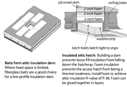
ü Build an insulation dam around the attic access hatch two inches above the height of the insulation. Build the dam with rigid materials like plywood or oriented-strand board so that the dam supports the weight of a person entering or leaving the attic.
ü If head space is limited at the hatch, use fiberglass batts to dam loose fill insulation.
4.2.2 Safety Preparations for Attic Insulation
Before insulating the attic, protect the heat-producing fixtures, such as recessed light fixtures and chimneys, by installing shields. Without shields, the light fixture or chimney might ignite the insulation. Or, the insulation might cause a light fixture or chimney to become hot enough to ignite something else.
The shielding enclosure must often serve as the air-seal for the chimney or light fixture.
Protecting Recessed Light Fixtures
There are three different types of recessed light fixtures and light-fan fixtures. (IC = insulation contact)
1. Non-IC-rated fixtures that must not touch insulation.
2. Type IC-rated fixtures that may be covered with fibrous insulation.
3. Type IC-AT, which are reasonably airtight (AT) and safe for contact by fibrous insulation.
Consider these options when preparing recessed light fixtures for attic insulation.
• Remove the recessed light fixture and replace it with a surface-mount fixture.
• Replace non-IC-rated fixtures with airtight IC-rated fixtures (IC-AT). You can cover these IC-AT fixtures with fibrous insulation after sealing the gap between the fixture and the surrounding materials.
• If the existing fixture is rated IC, you can seal the fixture’s enclosure to the ceiling with caulk and cover the fixture with fibrous insulation. Or you can shield the fixture with an enclosure, seal the enclosure to the ceiling with foam, and then cover the enclosure with insulation.
• Shield all existing non-IC-rated fixtures with airtight enclosures that extend above the level of the retrofitted insulation. Seal the enclosure to the ceiling with foam, and then surround the enclosure with insulation, but don’t insulate over its top.
• In cavities that are sheeted on both sides, either shield non-IC recessed lights or replace them before dense-pacing the cavities.
Caution: Spray foam insulation must not cover or surround recessed light fixtures or any other heat-producing devices.
Enclosing the Non-IC Fixture Remains
If an existing older recessed fixture, which isn’t labeled IC must remain in place, do these steps.
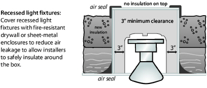
ü Build a Class I fire-resistant enclosure over the non-IC-rated fixture leaving at least 3 inches clearance from insulation on all sides and to the lid of the enclosure. The top of this fire-resistant enclosure must have an R-value of 0.5 or less and extend 4 inches above the level of the new insulation.
ü Notch the shields around wires.
ü Seal the enclosure to the ceiling with foam or caulk.
ü Don’t cover the top of the enclosure with insulation.
Protecting Chimneys
The requirements for protecting chimneys from contact with insulation vary widely from one building department to another. We know of three common approaches to insulating around chimneys, which are listed here beginning with the most restrictive.
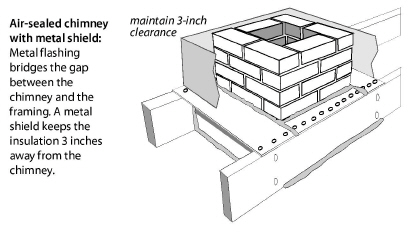
1. Air-seal around the chimney using non-combustible material like 26 gauge galvanized steel. Seal the steel to the chimney with a high-temperature sealant.
2. After air sealing gaps, install non-combustible insulation shields around masonry chimneys and manufactured metal chimneys to keep insulation at least 3 inches away from these chimneys.
3. A clearance smaller than 3 inches may be allowed if the attic insulation is non-combustible or if the specifications of the vent material allow a clearance less than 3 inches. For example: type B gas vent has a typical minimum clearance of 1 inch and all-fuel chimneys have a typical minimum clearance of 2 inches.
4. If the insulation is non-combustible, such as blown fiberglass or rock wool, no clearance between insulation and manufactured or masonry chimneys is necessary if this option is permitted by local building officials.
Electrical Junction Boxes
Observe these specifications during attic-insulation preparation.
1. Install covers on all electrical junction boxes that lack covers.
2. Use caulk or two-part foam to air seal electrical boxes that penetrate the ceiling (for light fixtures and fans), before blowing fibrous insulation over the boxes.
3. Flag the electrical boxes so that an electrician can find the boxes for future electrical work.
If knob-and-tube wiring is present in the attic, consider decommissioning it prior to installing insulation. See “Decommissioning Knob-and-Tube Wiring” on page 48.
4.2.3 Blowing Attic Insulation
Install attic insulation to a cost-effective R-value, depending upon existing insulation level and climatic region. Air seal attics before installing attic insulation. Air sealing may require removing existing insulation and debris that obstruct air sealing. See “Removing Insulation for Attic Air Sealing” on page 123.
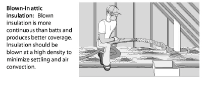
Blown insulation is usually better than batt insulation because blown insulation forms a seamless blanket. Blown fibrous attic insulation settles: cellulose settles 10% to 20% and fiberglass settles 3% to 10%. Blowing attic insulation at the highest achievable density helps minimize both settling and air circulation within the blown insulation.
Observe these specifications when blowing loose-fill attic insulation.
ü Calculate how many bags of insulation are needed to achieve the R-value specified on the work order from the table on the bag’s label.
ü Install insulation depth rulers: one for every 300 square feet.
ü Maintain a high density by moving as much insulation as possible through the hose with the available air pressure. The more the insulation is packed together in the blowing hose, the greater is the insulation’s installed density.
ü Fill the edges of the attic first, near the eaves or gable end, then fill the center.
ü When filling a tight eaves space, push the hose out to the edge of the ceiling. Allow the insulation to fill and pack against the baffle.
ü Install insulation to a consistent depth. Level the insulation with a stick if necessary.
ü Post an insulation certificate, with insulation type, number of bags installed, installed thickness, coverage area, and insulation R-value at the attic entrance. See “Insulation Receipt or Certificate” on page 98.
4.2.4 Closed-Cavity Attic Floors
|
SWS Detail: 4.1003.4 Cape Cod Side Attic Roof—Dense Pack Installation, 4.1005.6 Enclosed Attic Storage Platform Floor —Dense Pack Installation |
The ceiling joists in the attic are often covered by a wood floor for storage. You may have to remove some floor boards or drill the floor sheathing to install dense-packed insulation.
ü Inspect and thoroughly seal the floor cavity’s air leaks before blowing insulation.
ü Protect recessed light fixtures and other heat-producing devices in the floor cavity.
ü Then dense-pack fiberglass or cellulose insulation into the spaces between the ceiling joists.
ü Post an insulation certificate, with insulation type and number of bags installed, installed thickness, coverage area, and insulation R-value at the attic entrance. See “Insulation Receipt or Certificate” on page 98.
4.2.5 Insulating Closed Roof Cavities
Many homes have cathedral ceilings or flat roofs that are only partially filled with insulation. The IRC 2012 building code requires one of these two approaches to insulate a roof cavity.
1. Verify or provide a ventilated space of at least one inch between the roof insulation and the roof sheathing by providing soffit and ridge ventilation.
2. If no roof ventilation, then install foam roof insulation in addition to filling the cavity with insulation. Foam roof insulation in addition to the cavity insulation of between R-5 and R-35 depending on climate.
Many cathedral roof cavities have been dense-packed with fiberglass insulation without ventilation or foam roof insulation. Some experts believe that this is an effective solution. However, this solution usually requires engineered plans approved by the building department when a building permit is required.
Ventilated Closed Roof Cavities
Inspect the roof cavities for baffles that will maintain a one-inch air space between the new insulation and the roof deck.To prepare for roof-cavity insulation, without existing baffles and with a ventilated space above the insulation, use this procedure.
ü Remove either the roofing and sheathing or the interior ceiling to gain full access to the cavity.
ü Remove recessed light fixtures and replace them with surface-mounted light fixtures. Carefully patch and air seal the openings.
ü Install fiberglass or foam insulation to meet the IECC 2012 regional minimum roof-assembly R-value requirements.
ü Install openings into the ventilation channel above the insulation totaling 1/150 of the roof area. If the ceiling has a vapor barrier the requirement is reduced to 1/300 of the roof area.
ü In cold climates, install a vapor barrier at the ceiling. At minimum paint an oil-based primer over the interior drywall or plaster.
ü Repair roof leaks or install a new water-tight roof. Replace moisture-damaged sheathing as part of the roof replacement.
ü Install an air-barrier ceiling (drywall) if the existing ceiling isn’t an adequate air barrier, for example tongue-and-groove paneling.
ü Seal other air leaks with great care, especially at the perimeter and around ridge beams.
ü When replacing the roof, consider installing 1-to-8 inches of rigid high-density foam insulation on top of the roof deck. If you choose this option, dense-pack the existing roof cavity first.
Un-Ventilated Closed Roof Cavities: Decisions
Many homes have cathedral ceilings, vaulted ceilings, or flat roofs that are partially filled with insulation and would require removing the roof or the ceiling in order to install baffles for ventilation or rooftop foam board during retrofit cavity insulation.
Dense-packing the cavities prevent most convection and moist-air infiltration, which are leading causes of moisture problems in roof cavities.
Important Note: Dense-packing roof cavities with fiberglass insulation and without ventilation is controversial. The colder the climate, the higher the risk of problems, such as ice damming. However, dense-packing the cavities prevents most convection and moist-air infiltration, which are leading causes of moisture problems in roof cavities. Consult a knowledgeable local engineer before deciding to dense-pack a roof cavity with fiberglass. Don’t dense-pack roof cavities with cellulose because of its moisture absorption and its susceptibility to moisture damage.
Closed Roof Cavities: Preparation
To prepare for dense-packing the roof-cavity, consider the following steps.
ü Reduce or eliminate sources of moisture in the home. See "Solutions for Moisture Problems" on page 35.
ü Verify that the ceiling has a vapor retarder and air barrier on the interior. If not, install a vapor retarder and air barrier.
ü Remove recessed light fixtures and replace them with IC-AT fixtures or surface-mounted fixtures. Carefully patch and air seal the openings if you replace the recessed fixtures with surface-mounted ones.
ü Seal other ceiling air leaks, large and small, with great care.
ü When replacing the roof during roof-cavity insulation, consider installing 1-to-8 inches of rigid high-density foam insulation on top of the roof deck. If you replace the roof, dense-pack the existing roof cavity first.
ü Don’t insulate the roof deck without first filling the closed roof cavity beneath the roof because the roof assembly’s thermal resistance will be reduced by air convection inside the roof cavity.
Blowing Insulation into the Closed Roof Cavity
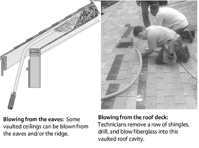
Always use a fill tube when blowing closed roof cavities. Insert the tube into the cavity to within a foot of the end of the cavity. Access the cavity through the eaves, the roof ridge, the roof deck, or the ceiling. Consider one of these procedures.
• Drilling holes in the roof deck after removing shingles or ridge roofing.
• Removing soffit and blowing insulation from the eaves.
• Drilling and blowing through a drywall ceiling.
• Carefully removing a tongue-and-groove plank and blowing insulation into cavities through this slot.
4.2.6 Exterior Rooftop Foam Insulation
Only install rooftop foam insulation over dense-packed roof cavities. A ventilation space between existing insulation and the new rooftop insulation reduces the foam’s R-value. Roofers use this method mainly when re-roofing low-sloping roofs.
ü Use high density foam board: 2 pcf for polystyrene or 3 pcf for polyisocyanurate if the roof is flat or low sloping.
ü Flash all external penetrations according to the roofing manufacturer’s specifications.
ü Use a cool roofing material such as white rubber or white metal to limit the foam’s temperature during intense summer sunshine and to minimize cooling costs.
ü Contact a design professional to make sure the roof will drain properly after foam installation.
ü Provide an insulation certificate, with insulation type and number of bags installed, installed thickness, coverage area, and insulation R-value at the attic entrance. See “Insulation Receipt or Certificate” on page 98.
Many foam manufacturers can taper expanded polystyrene foam, providing wedge-shaped pieces to create slope for drainage. See “Expanded Polystyrene (EPS) Foam Board” on page 108. See “Polyisocyanurate (PIC) Foam Board” on page 109.
4.2.7 Installing Fiberglass Batts in Attics
|
SWS Detail: 4.1005.3 Accessible Floors—Batt Insulation Over Existing Insulation |
Follow these specifications when installing fiberglass batts in an attic. Fiberglass batts aren’t the best insulation for attics because of all their seams.
ü When layering batts, install new layers at right angles to underlying layers if the top of the existing batts are level with or above the ceiling joist or truss bottom chord.
ü Install un-faced fiberglass insulation whenever possible.
ü If you must install faced batts, install them with the facing toward the heated space. Never install faced insulation over existing insulation.
ü Cut batts carefully to ensure a tight fit against the ceiling joists and other framing.
4.2.8 Cathedralized Attics (Open Cavity)
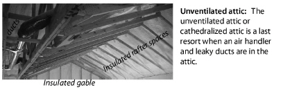
A cathedralized attic has insulation attached to the bottom of the roof deck and is also called a hot roof. Choose to insulate the bottom of the roof deck instead of insulating the ceiling when the building owner wants to use the attic or to enclose an attic air handler and leaky ducts within the home’s thermal boundary.
Important: Insulating the roof deck presents a risk of moisture problems from roof leaks or condensation. To avoid moisture condensation within the insulation or at the bottom of the roof deck during cold weather, use air-impermeable insulation such as closed-cell foam or install an air barrier and vapor retarder to the rafters.
Provide the client with an insulation certificate, with insulation type and number of bags installed, installed thickness, coverage area, and insulation R-value.See “Insulation Receipt or Certificate” on page 98.
Fiberglass Roof-Deck Insulation
Insulating the rafter space with an air-permeable insulation requires an air barrier, vapor retarder, and Class I (or A) fire-rated material at the roof cavity’s lower boundary. Consider these two alternatives.
1. Install the rafter’s depth of fiberglass batts and then a material or combination of materials that constitutes an air barrier, vapor retarder, and Class I fire barrier.
2. Blow dense-packed fiberglass insulation between the roof deck using a rigid sheeting or flexible insulation restraint. Dense-pack the fiberglass at a minimum of 2.0 pcf.
|
SWS Detail: 4.1003.1 Pitched/Vaulted/Cathedralized Ceilings—Loose Fill Over |
A vaulted attic is framed with a special truss that creates a sloping roof and a sloping ceiling. Access to the cavity varies from difficult to impossible. Install insulation from either the top of the roof deck or through the ceiling. Insulation, installed at the ceiling, must have some stability to prevent gravity from pulling it downhill or wind from piling it, leaving some areas under-insulated. Consider the following options to insulating uninsulated or partially insulated vaulted attics.
1. Insulate the ceiling with fiberglass batts. Install the batts parallel to the framing if the top of existing insulation is below the framing. Install the batts perpendicular to the framing if the top of the existing insulation is above the framing.
2. Insulate the bottom of the roof deck, as described previously for a cathedralized attic, if you remove the ceiling.
3. Insulate the ceiling with sprayed foam, damp-spray fibrous insulation, or batts from the roof with the roof sheathing removed.
4. Fill the cavity to approximately 100% with loosely blown fiberglass from indoors or through the roof.
5. Preserve or install openings into the ventilation space above the insulation totaling 1/150 of the roof area. If the ceiling has a vapor retarder the requirement is 1/300 of the roof area.
Whatever option you choose, provide the client with an insulation certificate, with insulation type and number of bags installed, installed thickness, coverage area, and insulation R-value See “Insulation Receipt or Certificate” on page 98.
4.2.10 Finished Knee Wall Attics
|
SWS Detail: 4.1004.1 Preparation for Dense Packing, 4.1005.1 Accessible Floors—Batt Installation |
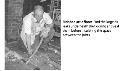
Finished attics require special care when installing insulation. They often include five separate sections that require different air-sealing and insulating methods. Seal air leaks in all these assemblies before insulating them. If necessary, remove the planking and insulation from the side-attic floor to expose the air leaks.
Use these specifications when insulating finished attics.
ü Seal large air leaks between conditioned and non-conditioned spaces.
ü Inspect the structure to confirm that it has the strength to support the weight of the insulation.
ü Insulate access hatches to the approximate R-value of the assembly through which it is located.
ü Post an insulation certificate, with insulation type and number of bags installed, installed thickness, coverage area, and insulation R-value at the attic entrance. See “Insulation Receipt or Certificate” on page 98.
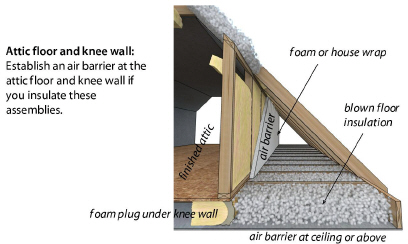
Attic Floor
There are a number of options for insulating the attic floor of a finished attic with knee walls. By attic floor, we mean the ceiling of the living space below with its ceiling joists and any floor sheeting installed over the joists for a storage platform.
• Install blown fibrous insulation over the ceiling, which should be an air barrier.
• Install blown fibrous insulation over existing insulation.
• Install fiberglass batts over the ceiling, which should be an air barrier.
• Install fiberglass batts over the existing insulation.
Whichever of these options that you choose, do the necessary air sealing to the attic floor before installing insulation. Also observe the preparations and safety precautions discussed in “Preparing for Attic Insulation” on page 129 and “Safety Preparations for Attic Insulation” on page 131.
Exterior Walls of Finished Attic
Insulate these walls as described in “Retrofit Closed-Cavity Wall Insulation” on page 176 or “Open-Cavity Wall Insulation” on page 180.
Collar-Beam Attic
Insulate this type of half-story attic as described in “Blowing Attic Insulation” on page 135.
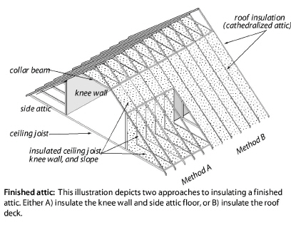
Sloped Roof
Insulate sloped roof with densepack fiberglass or cellulose insulation. Install plugs of fiberglass batt, or other vapor permeable material, at the ends of this cavity to contain the blown insulation while allowing it to breathe.
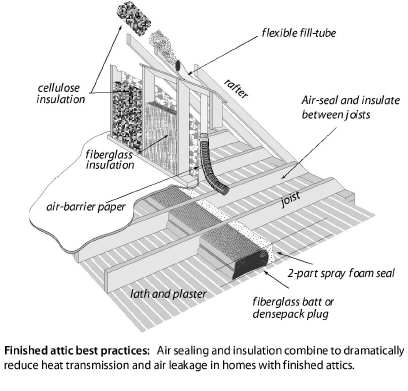
Insulate knee walls using any of these methods.
• Install un-faced fiberglass batts and cover the insulation with house wrap on the attic side. Prefer R-13 or R-15, 3.5-inch fiberglass batts.
• Install the house wrap or another insulation restrainer first and reinforce it with wood lath. Then blow dense-packed fibrous insulation into the cavity through the house wrap and patch the house wrap with tape. (Cellulose: 3.5 pcf; fiberglass 2.2 pcf)
• Spray the cavities with open-cell or closed-cell polyurethane foam after gaining access to the cavities and removing surface dirt to ensure good adhesion.
• For knee walls without framing, mechanically fasten rigid insulation to the wall’s surface and seal the seams.
Post an insulation certificate, with insulation type and number of bags installed, installed thickness, coverage area, and insulation R-value at the attic entrance. See “Insulation Receipt or Certificate” on page 98.
Preparation for Kneewall Insulation
Make whatever repairs and seal air leaks before installing the knee-wall insulation.
ü Seal all large air leaks with structural materials.
ü Seal all joints, penetrations, and other potential air leaks in the cavities with caulk or foam.
ü Before installing caulk or spray foam insulation, clean dust and any other material that might interfere with the spray foam’s adhesion.
Air Sealing and Insulating under the Knee Wall
To seal and insulate under the knee wall, create an airtight and structurally strong seal in the joist spaces under the knee wall. Consider these options.
• Install sealed wood blocking between the floor joists covered with spray foam.
• Insert 2-inch-thick foam sheets and foam their perimeters with one-part or two-part foam.
• Insert a fiberglass batt into the cavity and foam its face with an inch of two-part closed-cell spray foam.
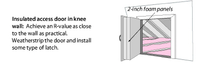
4.2.12 Access Doors in Vertical Walls
For kneewall access doors, observe the following.
ü Insulate knee-wall access hatches and collar-beam access hatch with 3 or more inches of rigid-foam insulation. Or install a fiberglass batt stapled to the access door in such a way as to not compress the fiberglass batt.
ü Weatherstrip the hatch and install a latch or other method to hold the access door closed against the weatherstrip.
4.2.13 Walk-Up Stairways and Doors
Think carefully about how to install a continuous insulation blanket and air barrier around or over the top of an attic stairway. If you enter the attic by a stairwell and standard vertical door, use these instructions.
ü Blow dense-pack fibrous insulation into walls of the stairwell.
ü Install a threshold or door sweep, and weatherstrip the door.
ü Insulate or replace the door with an insulated door if cost effective.
ü Blow dense-packed insulation into the sloping cavity beneath the stair treads and risers.
You can also establish the thermal boundary at the ceiling level, but this requires a horizontal hatch at the top of the stairs.
When planning to insulate stairwells, investigate barriers such as fire blocking that might prevent insulation from filling cavities you want to fill. Also consider what passageways may lead to areas you don’t want to fill such as closets.
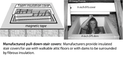
4.2.14 Insulating & Sealing Pull-Down Attic Stairways
Pull-down attic stairways are sometimes installed above the access hatch. Building a foam-insulated box or buying a manufactured stair-and-hatchway cover are good solutions to insulating and sealing this weak point in the ceiling insulation. Install weatherstripping around the insulated box.
Educate the client on the purpose and operation of stair-and-hatchway cover, and ask them to carefully replace it when they access the attic.
|
SWS Details: 4.1088.4 Parapet Walls—Dense Pack, 4.1088.5 Parapet Walls—Spray Polyurethane Foam (SPF) |
Parapet walls are a continuation of exterior walls that rise above the roof. Parapet walls are often an air-leakage and thermal bridging problem because the insulation and air barrier aren’t continuous between the exterior wall and roof.
Inspect the parapet area from both indoors and outdoors and decide how to connect the wall insulation and air barrier with the roof insulation and air barrier. Consider these two alternatives.
1. Install an air barrier and dense-pack the wall cavity of the parapet.
2. Spray foam the parapet to connect the insulation and air barrier of the exterior wall with attic or roof insulation and air barrier.
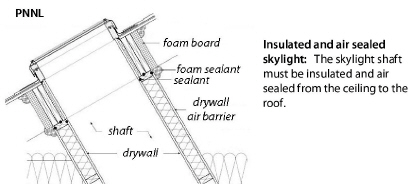
Skylights are places where the insulation and air barrier may not be continuous. Inspect the insulation and air barrier of the skylight shaft. Install insulation and air seals as necessary to make a continuous insulated and air-sealed assembly as shown in the illustration.
Whole-house fans can create significant thermal bridging if they aren’t dammed and insulated thoroughly around their perimeter. Whole-house fans can leak a lot of air if they lack an airtight seasonal cover.
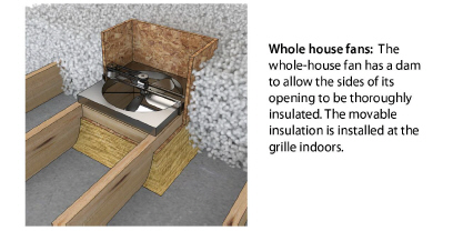
ü Build a foam panel as thick as practical and install it inside the whole-house fan’s frame from indoors.
ü Use clips or other restrainers to hold the panel in place.
ü Install weatherstrip around the perimeter to limit air leakage.
|
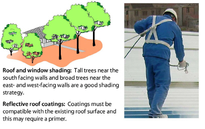
SWS Detail:5.3202.2 Reflective Roof Coatings, 5.3202.1 Reflective Coatings on Metal Roofs |
Homes with reflective roof coatings, along with at least R-19 insulation and good attic ventilation, may show two-thirds less solar heat gain than those buildings with darker roofs, little insulation, and poor ventilation.
The best cool roofs must both reflect solar heat and also effectively emit or release solar heat that accumulates in the roof assembly. The concept of emittance informs us that some materials reflect heat well but don’t release heat effectively. Their emittance prevents shiny metal materials from being efficient cool-roof materials.
Scientists at Lawrence Berkeley Laboratory created an index for comparing the coolness of roofing materials that combines both reflectance and emittance into a rating more predictive of air-conditioning energy savings. The solar reflectance index (SRI) ranges from a little less than 0 to a little more than100. High SRI numbers are better than low numbers.
Standard white asphalt shingles have an SRI of only 20 to 25 when new, and that degrades over time due to loss of white granules and dirt deposits. Darker asphalt roofs have SRIs as low as 1.0 (they absorb almost all the solar heat that strikes them). White metal roofs have good SRIs from 70 to 82.
Bare galvanized steel and aluminum aren’t nearly as cool as white roofing. Those shiny metals reflect solar heat well, but they don’t emit heat effectively so they tend to heat up, resulting in SRIs in the 40s for bare galvanized steel and in the 70s for bare aluminum.
Compared to poorly ventilated roofs, good roof ventilation helps to keep attic temperatures lower. But expect less savings from improving attic ventilation compared to cool roofs and other sun-blocking measures, because radiant heat transfer —not air convection — dominates attic heat gain.
Well-planned landscaping can reduce an unshaded building’s summer air-conditioning costs by 15% to 50%. However, poor tree siting or careless tree selection is common, so consult with landscaping experts during planning and planting.
Studies by the Lawrence Berkeley Laboratory found summer daytime air temperatures 3°F to 6°F lower in neighborhoods with mature tree canopies compared to newly developed areas with no trees.
A tree can produce daily cooling effects similar to five average-sized air conditioners running 20 hours per day. Shading and evapotranspiration — the process by which a tree releases water vapor — can reduce air temperatures as much as 9°F compared to unshaded areas.
|
Roofing type |
Reflectance |
SRI index |
|---|---|---|
|
White elastomeric coating (low slope) |
.70 to .85 |
87 to 107 |
|
White EPDM rubber membrane (low slope) |
.70 to .80 |
80 to 105 |
|
White clay tile |
.70 |
90 |
|
White rubber membrane |
.70 |
84 |
|
White metal |
.60 to .70 |
82 |
|
New aluminum metal |
.60 |
71 |
|
New galvanized steel |
.60 |
46 |
|
Colored clay tile |
.20 to .50 |
20 to 60 |
|
White asphalt shingles |
.20 to .30 |
21 to 40 |
|
Colored asphalt shingles |
Š0.20 |
–2 to 22 |
|
Black EPDM rubber membrane (low slope) |
.06 |
–1 |
|
Higher numbers are better: a high reflectance or high SRI yields low cooling costs. An Energy Star rating (in 2008) requires an SRI of 25 or higher for steep-sloped roofs, and an SRI of 65 or higher for low-slope roofs. |
||