Appendices
A–1 R-values for Common Materials
|
Material |
R-value |
|---|---|
|
Fiberglass or rock wool batts and blown 1” |
2.8–4.0 |
|
Blown cellulose 1” |
3.0–4.0 |
|
Vermiculite loose fill 1” |
2.7 |
|
Perlite 1” |
2.4 |
|
White expanded polystyrene foam (beadboard) 1” |
3.9–4.3 |
|
Polyurethane/polyisocyanurate foam 1” |
6.2–7.0 |
|
Extruded polystyrene 1” |
5.0 |
|
High-density 2-part polyurethane foam 1” |
5.8–7.5 |
|
Low-density 2-part polyurethane foam 1” |
3.6 |
|
Oriented strand board (OSB) or plywood 1/2” |
1.6 |
|
Concrete or stucco 1” |
0.1 |
|
Wood 1” |
1.0 |
|
Carpet/pad 1/2” |
2.0 |
|
Wood siding 3/8–3/4” |
0.6–1.0 |
|
Concrete block 8” |
1.1 |
|
Asphalt shingles |
0.44 |
|
Fired clay bricks 1” |
0.1–0.4 |
|
Gypsum or plasterboard 1/2” |
0.4 |
|
Single pane glass 1/8” |
0.9 |
|
Low-e insulated glass (Varies according to Solar Heat Gain Coefficient (SHGC) rating.) |
3.3–4.2 |
|
|
Rated Fan CFM |
|||||||
|
|
50 |
80 |
100 |
125 |
150 |
200 |
250 |
300 |
|
|
|
|
|
|
|
|
|
|
|
Duct Dia. |
Smooth Hard Duct - Maximum Duct Length in Feet |
|||||||
|
3” |
5 |
X |
X |
X |
X |
X |
X |
X |
|
4” |
114 |
31 |
10 |
X |
X |
X |
X |
X |
|
5” |
NL |
152 |
91 |
51 |
28 |
X |
X |
X |
|
6” |
NL |
NL |
NL |
168 |
112 |
53 |
25 |
9 |
|
7” |
NL |
NL |
NL |
NL |
NL |
148 |
88 |
54 |
|
8” |
NL |
NL |
NL |
NL |
NL |
NL |
198 |
133 |
|
|
|
|
|
|
|
|
|
|
|
Duct Dia. |
HVAC Flex Duct - Maximum Duct Length in Feet |
|||||||
|
3” |
X |
X |
X |
X |
X |
X |
X |
X |
|
4” |
56 |
4 |
X |
X |
X |
X |
X |
X |
|
5” |
NL |
81 |
42 |
16 |
2 |
X |
X |
X |
|
6” |
NL |
NL |
158 |
91 |
55 |
18 |
1 |
X |
|
7” |
NL |
NL |
NL |
NL |
161 |
78 |
40 |
19 |
|
8” |
NL |
NL |
NL |
NL |
NL |
189 |
111 |
69 |
|
NL: No limit; X: not allowed Table assumes no elbows. Deduct 15 ft from allowable duct length for each elbow. |
||||||||
|
Test/Rating |
Description |
|---|---|
|
ASTM E-136 or E-176 |
If a material passes this test, it is non-combustible. |
|
ASTM E-119 |
Hourly rating of a wall when exposed to fire. Determines how long that the wall holds back heat and flames and maintains its structural integrity. |
|
ASTM E-184 |
Hourly rating for a sealant system for a penetration through a fire-rated (ASTM E119) assembly. |
|
ASTM E-84 |
Test measures how fast flames spread in a fire tunnel lined with the tested material, compared to red oak, which is given a flame spread of 100. This test classifies materials as Class I, II, or III (or A, B, & C) See flame spread in the three rows below. |
|
Class I or A |
Flame spread less than or equal to 25 |
|
Class II or B |
Flame spread 26 to 75 |
|
Class III or C |
Flame spread 76 to 200 |
|
FM 4880 or UL-1040 |
The fire burns in a 90-degree corner of a wall assembly containing the tested material. Approximates the performance of a material installed in a typical building assembly. The test measures the fire resistance of an assembly in 15 minutes of fire exposure at 40 kW and 160 kW. |
|
ISO 9705 UL 1715 |
Like the corner test except the fire burns in a room with its wall and ceiling assembly sheeted with the tested finish material. The measures time with flame spread and smoke developed ratings relative to Class I, II, and III assemblies. |
|
UL181 |
Duct materials, duct-closure systems, and duct sealants so labeled pass UL fire-resistance tests. |
A–6 DOE Health and Safety Guidance
Weatherization Program Notice 17-7 is Effective August 9, 2017. WPN 17-7 clarifies, updates, and provides additional information related to the implementation and installation of health and safety (H&S) measures as part of the DOE WAP. This guidance also provides required components for Grantees to include in their Health and Safety Plans.
WAPTAC provides the WPN 17-7 documents at:
http://www.waptac.org
Rules & Guidance
>> Program Guidelines
>> 2017 Program Guidance Documents
>> WPN 17-7: Weatherization Health and Safety Guidance
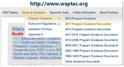
Resource Links
• WPN 17-7: Weatherization H&S Guidance
• Attachment A- Additional H&S Guidance Related to Heating Systems
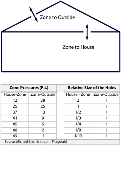
A–7 Pressure Diagnostics – Hole Size Ratios
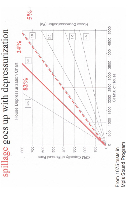
A–8 House Depressurization Chart