Appendices
A–1 R-values for Common Materials
|
Material |
R-value |
|---|---|
|
Fiberglass or rock wool batts and blown 1” |
2.8–4.0 |
|
Blown cellulose 1” |
3.0–4.0 |
|
Vermiculite loose fill 1” |
2.7 |
|
Perlite 1” |
2.4 |
|
White expanded polystyrene foam (beadboard) 1” |
3.9–4.3 |
|
Polyurethane/polyisocyanurate foam 1” |
6.2–7.0 |
|
Extruded polystyrene 1” |
5.0 |
|
High-density 2-part polyurethane foam 1” |
5.8–6.6 |
|
Low-density 2-part polyurethane foam 1” |
3.6 |
|
Oriented strand board (OSB) or plywood 1/2” |
1.6 |
|
Concrete or stucco 1” |
0.1 |
|
Wood 1” |
1.0 |
|
Carpet/pad 1/2” |
2.0 |
|
Wood siding 3/8–3/4” |
0.6–1.0 |
|
Concrete block 8” |
1.1 |
|
Asphalt shingles |
0.44 |
|
Fired clay bricks 1” |
0.1–0.4 |
|
Gypsum or plasterboard 1/2” |
0.4 |
|
Single pane glass 1/8” |
0.9 |
|
Low-e insulated glass (Varies according to Solar Heat Gain Coefficient (SHGC) rating.) |
3.3–4.2 |
|
|
Rated Fan CFM |
|||||||
|
|
50 |
80 |
100 |
125 |
150 |
200 |
250 |
300 |
|
|
|
|
|
|
|
|
|
|
|
Duct Dia. |
Smooth Hard Duct - Maximum Duct Length in Feet |
|||||||
|
3” |
5 |
X |
X |
X |
X |
X |
X |
X |
|
4” |
114 |
31 |
10 |
X |
X |
X |
X |
X |
|
5” |
NL |
152 |
91 |
51 |
28 |
X |
X |
X |
|
6” |
NL |
NL |
NL |
168 |
112 |
53 |
25 |
9 |
|
7” |
NL |
NL |
NL |
NL |
NL |
148 |
88 |
54 |
|
8” |
NL |
NL |
NL |
NL |
NL |
NL |
198 |
133 |
|
|
|
|
|
|
|
|
|
|
|
Duct Dia. |
HVAC Flex Duct - Maximum Duct Length in Feet |
|||||||
|
3” |
X |
X |
X |
X |
X |
X |
X |
X |
|
4” |
56 |
4 |
X |
X |
X |
X |
X |
X |
|
5” |
NL |
81 |
42 |
16 |
2 |
X |
X |
X |
|
6” |
NL |
NL |
158 |
91 |
55 |
18 |
1 |
X |
|
7” |
NL |
NL |
NL |
NL |
161 |
78 |
40 |
19 |
|
8” |
NL |
NL |
NL |
NL |
NL |
189 |
111 |
69 |
|
NL: No limit; X: not allowed Table assumes no elbows. Deduct 15 ft from allowable duct length for each elbow. |
||||||||
|
Test/Rating |
Description |
|---|---|
|
ASTM E-136 |
If a material passes this test, it is non-combustible. |
|
ASTM E-119 |
Hourly rating of a wall when exposed to fire. Determines how long that the wall holds back heat and flames and maintains its structural integrity. |
|
ASTM E-184 |
Hourly rating for a sealant system for a penetration through a fire-rated (ASTM E119) assembly. |
|
ASTM E-84 |
Test measures how fast flames spread in a fire tunnel lined with the tested material, compared to red oak, which is given a flame spread of 100. This test classifies materials as Class I, II, or III (or A, B, & C) See flame spread in the three rows below. |
|
Class I or A |
Flame spread less than or equal to 25 |
|
Class II or B |
Flame spread 26 to 75 |
|
Class III or C |
Flame spread 76 to 200 |
|
FM 4880 or UL-1040 |
Like ASTM E-84 except the fire burns in a 90-degree corner of a wall assembly containing the tested material. These tests are designed to closer approximate actual performance of a material installed in a typical building assembly. The flame spread and smoke developed ratings also relative to Class I, II, and III assemblies. |
|
UL 1715 |
Like the tunnel test and corner test except the fire burns in a room with its wall and ceiling assembly containing the tested material. The flame spread and smoke developed ratings also relative to Class I, II, and III assemblies. |
|
UL181 |
Duct materials, duct-closure systems, and duct sealants so labeled pass UL fire-resistance tests. |
A–4 SWS Maximum CAZ Depressurization
|
Appliance Type |
Max. Depress. |
|---|---|
|
Atmospheric water heater only (Category I, natural draft), open-combustion appliances |
–2 Pa |
|
Atmospheric water heater (Category I, natural draft) and atmospheric furnace (Category I, natural draft), common-vented, open-combustion appliances |
–3 Pa |
|
Gas furnace or boiler, Category I or Category I fan-assisted, open-combustion appliances |
–5 Pa |
|
Oil or gas unit with power burner, low- or high-static pressure burner, open combustion appliances |
–5 Pa |
|
Closed, controlled wood-burning appliances |
–7 Pa |
|
Induced-draft appliances (fan at point of exit at wall), Category I with induced draft, open-combustion appliances |
–15 Pa |
|
Pellet stove with draft fan and sealed vent |
–15 Pa |
|
Gas appliances, Category III vented through the wall, forced draft, open-combustion appliances |
–15 Pa |
|
Direct-vent, sealed combustion appliances with forced draft |
–25 Pa |
|
SWS Detail: 2.0299.1 Combustion Appliance Depressurization Limits Table |
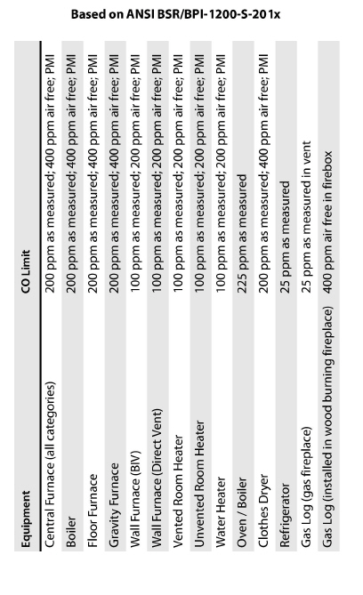
A–6 BPI CO & Draft Decision Table
|
CO Level
|
|
Draft and Spillage |
Required Action |
|---|---|---|---|
|
0 – 25 ppm |
and |
Passes |
Proceed with work.
|
|
26 –100 ppm |
and |
Passes |
Recommend that the CO problem be fixed.
|
|
26 –100 ppm |
and |
Fails at worst-case only |
Recommend a service call for the appliance and/or repairs to the home to correct the problem. |
|
100 –400 ppm |
or |
Fails under normal conditions |
Stop Work: Work may not proceed until the system is serviced and the problem is corrected. |
|
>400 ppm |
and |
Passes |
Stop Work: Work may not proceed until the system is serviced and the problem is corrected. |
|
>400 ppm |
and |
Fails under any conditions |
Emergency: Shut off the fuel to the appliance and ask the homeowner to call for service immediately. |
|
Building Performance Institute Inc.: Energy Analyst Standard |
|||
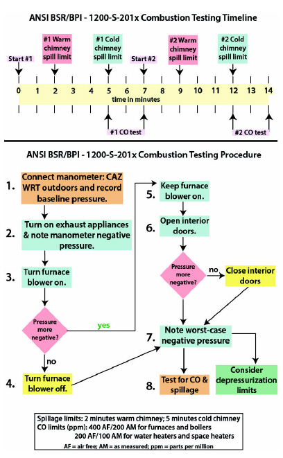
A–8 BPI Combustion-Testing Diagrams
A–9 DOE Health and Safety Guidance
Weatherization Program Notice 17-7 is Effective August 9, 2017. WPN 17-7 clarifies, updates, and provides additional information related to the implementation and installation of health and safety (H&S) measures as part of the DOE WAP. This guidance also provides required components for Grantees to include in their Health and Safety Plans.
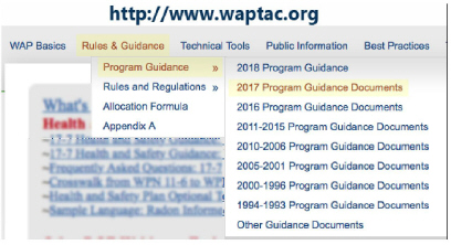
WAPTAC provides the WPN 17-7 documents at:
http://www.waptac.org
Rules & Guidance
>> Program Guidelines
>> 2017 Program Guidance Documents
>> WPN 17-7: Weatherization Health and Safety Guidance
Resource Links
• WPN 17-7: Weatherization H&S Guidance
• Attachment A- Additional H&S Guidance Related to Heating Systems