8.3 Heating System Replacement
This section discusses replacing combustion furnaces and boilers. We’ll also discuss gas heating-replacement and oil-heating-replacement specifications.
8.3.1 Combustion Furnace Replacement
|
SWS Detail: 5.3001.1 Load Calculation and Equipment Selection, 5.3001.2 Ductwork and Termination Design, 5.3002.1 Preparation for New Equipment, 5.3003.1 Data Plate Verification |
This section discusses air handlers of combustion furnaces and also heat pumps. Successful air-handler replacement requires selecting the right heat (and cooling) input, blower model, and blower speed. The installation must include making repairs to ducts and other remaining components, and testing to verify that the new air handler operates correctly.
Preparation
ü Recover refrigeration in the existing heating-cooling unit according to EPA regulations.
ü Disconnect and remove the furnace or heat pump, attached air-conditioning equipment, and other materials that won’t be reused.
ü Transport these materials off the customer’s property to a recycling facility.
ü Verify that all accessible ducts were sealed as part of the furnace’s installation, including the air handler, the plenums, and the branch ducts.
Equipment Selection
ü Evaluate the building to determine the correct size of the furnace, using ACCA Manual J or equivalent method.
ü Select the air handler using ACCA Manual S or equivalent method along with manufacturers’ air-handler specifications.
ü Select the supply and return registers using ACCA Manual T or equivalent method.
Air-Handler Installation
ü Install MERV 6 or higher filter in the new furnace.
ü The filter retainer must hold the filter firmly in place.
ü The filter must be easy to replace.
ü The filter must provide complete coverage of blower intake or return register. Filter compartment must not permit air to bypass the filter.
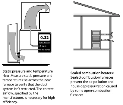
ü If flue-gas temperature or supply air temperature are unusually high, check static pressure and fuel input. See “Ducted Air Distribution” on page 288.
ü Attach the manufacturer’s literature including, operating manual and service manual, to the furnace.
Supporting Air Handlers
Support the new air handlers using these specifications.
• Support horizontal air handlers from below with a non-combustible, water-proof, and non-wicking material. Or support the horizontal air handler with angle iron and threaded rod from above.
• Support upflow air handlers with a non-combustible material from below when necessary to hold it above a damp basement floor.
• Support downflow air handlers with a strong, airtight supply plenum. Insulate this supply plenum on the exterior of the plenum.
8.3.2 Gas-Fired Heating Installation
The goals of gas-appliance replacement are to save energy and improve heating safety. The heating replacement project should produce a gas-fired heating system in virtually new condition, even though existing components like the gas lines, chimney, pipes, or wiring may remain.
Include maintenance or repair of existing components as part of the installation. Analyze design defects in the original system, and correct the defects during the heating system’s replacement.
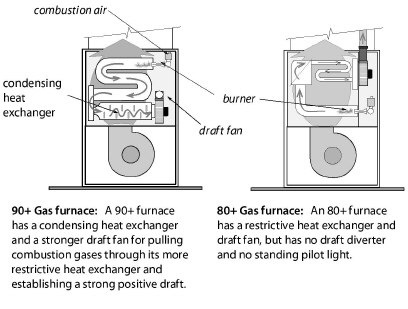
• If possible, install a condensing sealed-combustion (direct vent) furnace or boiler with a 90+ AFUE.
• Install non-condensing furnaces and boilers with a minimum AFUE of 80% if the 90% replacement unit isn’t cost-effective or practical.
• Install new gas-fired unit with adequate clearances to allow maintenance.
• Follow manufacturer’s venting instructions along with the National Fuel Gas Code (NFPA 54) to install a proper venting system. See “Inspecting Venting Systems” on page 270.
• Check clearances of the heating unit and its vent connector to nearby combustibles, according to NFPA 54. See page 270.
• Measure the new unit’s gas input and adjust the gas input if necessary.
Testing New Gas-Fired Heating Systems
ü Do a combustion test, and adjust fuel-air mixture to minimize O2. However don’t allow CO beyond 200 ppm as measured or 400 ppm air-free with this adjustment. See pages 227 and 255.
ü Verify that the gas water heater vents properly after installation of a sealed-combustion or horizontally vented furnace or boiler. Install a chimney liner if necessary to provide right-sized venting for the water heater.
8.3.3 Combustion Boiler Replacement
|
SWS Details: 2.0105.1 Combustion Worker Safety, 5.3001.1 Load Calculation and Equipment Selection, 5.3101.2 Space Load Calculation—Heat Emitter Sizing |
Technicians replace boilers as an energy-conservation measure or for health and safety reasons.
Boiler piping and controls present many options for zoning, boiler staging, and energy-saving features. Dividing homes into zones, with separate thermostats, can significantly improve energy efficiency compared to operating a single zone.
Follow these specifications when recommending a replacement boiler.
Design
A boiler’s seasonal efficiency is more sensitive to correct sizing than is a furnace’s efficiency.
ü Determine the correct size of the boiler, using ACCA Manual J and considering the installed radiation surface connected to the boiler.
ü Consider weatherization work that reduced the heating load serviced by the previous boiler when sizing the new boiler.
ü Size new radiators according to room heat loss and design water temperature.
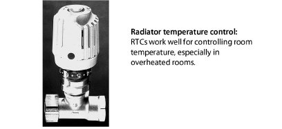
ü Specify radiator temperature controls (RTCs) for areas with a history of overheating.
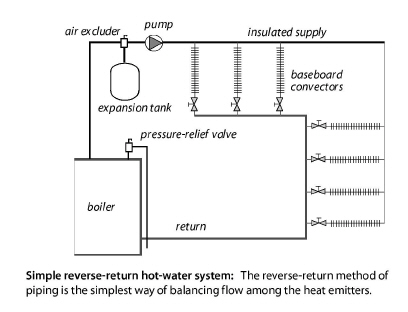
ü A functioning pressure-relief valve, expansion tank, air-excluding device, back-flow preventer, and an automatic fill valve must be part of the new hydronic system.
Pump and Piping
ü Verify that all supply piping is insulated with foam or fiberglass pipe insulation.
ü Suggest that the pump be installed near the downstream side of the expansion tank to prevent the suction side of the pump from depressurizing the piping, which can pull air into the piping system.
ü Replace the expansion tank, unless it’s the proper size for the new system. Adjust the expansion tank for the correct pressure during boiler installation. See page 316.
ü Extend new piping and radiators to conditioned areas, like additions and finished basements, which are currently heated by space heaters.
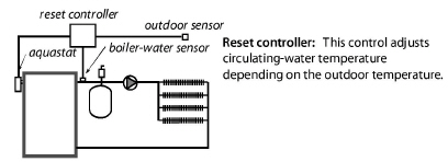
Controls
ü Maintaining a low-limit boiler-water temperature is wasteful. Boilers should be controlled for a cold start, unless the boiler is used for domestic water heating.
ü For large boilers, install reset controllers that adjust supply water temperature according to outdoor temperature and prevent the boiler from firing when the outdoor temperature is above a setpoint where heat isn’t needed.
ü Verify that return-water temperature is above 130° F for gas and above 150° F for oil, to prevent acidic condensation within the boiler, unless the boiler is designed for condensation. Install piping bypasses, mixing valves, primary-secondary piping, or other strategies, as necessary, to prevent condensation within a non-condensing boiler.
Combustion Testing
ü Inspect the chimney and upgrade it if necessary.
ü Verify that flue-gas oxygen and temperature are within the ranges specified in these two tables.
a. “Combustion Standards for Gas Furnaces and Boilers” on page 238
b. “Minimum Oil Burner Combustion Standards” on page 261
Steam Boilers
Steam-boiler performance is heavily dependent on the performance of the existing steam distribution system. The boiler installer should know how the distribution system performed when it was connected to the old boiler.
The new boiler’s water line should be at the same height as the old boiler’s water line, or the installers should know how to compensate for the difference in water-line levels. See "Steam Heating and Distribution" on page 319.
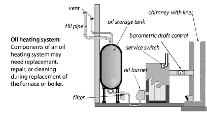
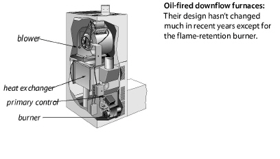
8.3.4 Oil-Fired Heating Installation
|
SWS Detail: 2.0201.2 Combustion Safety, 2.0203.3 Draft Regulation—Category I Appliance, 5.3003.9 Heating and Cooling Controls, 5.3003.4 Evaluating Electrical Service |
Oil-heating replacement should provide an oil-fired heating system in virtually new condition, even though components like the oil tank, chimney, piping, and wiring may remain in place.
Any maintenance or repair for these remaining components should be part of the replacement job. Analyze design defects of the original system, and correct them during the heating-system replacement.
ü New oil-fired furnaces and boilers should have an AFUE of 83%.
ü Install new oil-fired furnaces and boilers with adequate clearances to facilitate maintenance.
ü Inspect the existing chimney and the vent connector. Re-place the vent connector with Type L double-wall vent pipe.
ü Install a stainless steel chimney liner if necessary. See "Special Venting Considerations for Gas" on page 280.
ü Verify that the clearances between the vent connector and nearby combustibles are adequate. See “Clearances to Combustibles for Vent Connectors” on page 272.
ü Install a new fuel filter, and purge the fuel lines as part of the new installation.
Controls
ü Verify that a working emergency shut-off is installed in the living space.
ü Look for a control that interrupts power to the burner in the event of a fire.
ü Measure the transformer voltage to verify that it complies with the manufacturer’s specifications.
ü Measure the control circuit amperage, and adjust the thermostat’s heat anticipator to match the amperage. Or, follow the thermostat manufacturer’s instructions for adjusting cycle length.
Testing New Oil-Fired Heating Systems
ü Measure the oil pressure.
ü Look for the oil nozzle’s gallon-per-minute (gpm) rating.
ü Adjust oil pressure or replace nozzle as necessary to produce the correct input and to limit the flue-gas temperature.
ü Verify that the spray angle and spray pattern fit the size and shape of the combustion chamber.
ü Adjust oxygen, flue-gas temperature, and smoke number to match manufacturer’s specifications or specifications given here. Smoke number should be zero on all modern oil-fired equipment.
Inspect the oil tank, and remove dirt and moisture at bottom of the tank. Verify that the oil tank and oil lines comply with NFPA 31.
Oil tanks are now almost always installed above ground. But many old oil tanks are still buried. Inspect above-ground tanks to find leaks.
Below-ground tanks and above-ground tanks can both be evaluated by tests for water in the fuel system.
1. Start by inspecting the oil filter for corrosion. Corrosion in the oil filter indicates a high probability of water and corrosion in the tank.
2. Next use water-finding paste, applied to the end of a probe, to detect water at the bottom of the oil tank. For indoor tanks, you’ll need a flexible probe because of the ceiling-height limitations.
See also NFPA 31 Chapter 7 Fuel Oil Tanks.
Inspecting Above-Ground Oil Tanks
Indoor oil leaks are usually accompanied by petroleum smells. Inspect the oil tank as well as all the oil piping between the oil tank and the oil-fired furnace.
ü Look for different colors on the tank from condensation, corrosion, or fuel leaks.
ü Look at the bottom of the oil tank and see if oil is dripping from a leak.
ü Look for patches from previous leaks.
ü If the oil tank is new, don’t mistake previous oil-tank leaks for leaks in the new tank.
ü Use the water test described previously.
If you smell oil but you can’t see the leak, consider the following tests.
ü Use the water test described previously.
ü For hidden leaks, consider ultrasound leak detection by a oil-tank specialist.
Advice for Below-Ground Oil Tanks
Leaky below-ground oil tanks are a financial problem and a major environmental problem. Local, state, or federal authorities may require homeowners to remove the tank, abandon it in place, or have it leak-tested by one of the following methods.
ü Use the water testing described previously.
ü A tank specialist collects multiple soil samples from around the tank and analyzes them for petroleum contamination by an approved method.