12.2 Single-Family Airtightness Testing
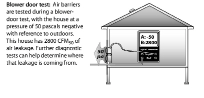
House airtightness testing was made possible by the development of the blower door. The blower door measures a home’s leakage rate at a standard pressure of 50 pascals. Energy auditors use this leakage measurement to compare homes with one another and to established air-leakage standards.
The blower door also allows the auditor to test parts of the home’s air barrier to locate air leaks. Sometimes air leaks are obvious. More often, the leaks are hidden, and you need a blower door to find their location.
This section outlines the basics of blower door measurement along with some techniques for gathering clues about the location of air leaks.
The blower door creates a 50-pascal pressure difference across the building shell and measures fan pressure in order to calculate airflow in cubic feet per minute (CFM50) to estimate the leakiness of homes. The blower door also creates pressure differences between rooms in the house and intermediate zones like attics and crawl spaces. These pressure differences can give clues about the location and combined size of a home’s hidden air leaks.
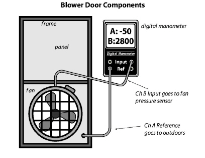
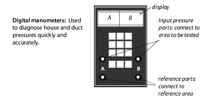
Connecting the digital manometer’s hoses correctly is essential for accurate testing.
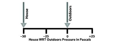
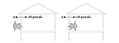
This method uses the phrase with-reference-to (WRT), to distinguish between the input zone and reference zone for a particular measurement. The outdoors is the most commonly used reference zone for blower door testing. The reference zone is considered to be the zero point on the pressure scale.
For example, house WRT outdoors = –50 pascals means that the house (input) is 50 pascals negative compared to the outdoors (reference or zero-point). This pressure reading is called the house pressure.
Low-Flow Rings
During the blower door test, the manometer measures airflow through the fan. This airflow (CFM50) is the primary measurement of a home’s airtightness and is directly proportional to the surface area of the home’s air leaks. For the blower door to measure airflow accurately, the air must be flowing at an adequate speed. Tighter buildings and smaller buildings don’t have enough air leakage to create an adequate airspeed to create the minimum fan pressure. This low-flow condition requires using one or two low-flow rings, to reduce the blower-door fan’s opening and to increase air speed, fan pressure, and measurement accuracy.
When the air speed is too low, the DG-700 displays “LO” in the Channel B display. After installing one of the low-flow rings, follow the manufacturer’s instructions for selecting the proper range or configuration on the digital manometer.
12.2.2 Preparing for a Blower Door Test
Preparing the house for a blower door test involves putting the house in its normal heating-season operation with all conditioned zones open to the blower door. Try to anticipate safety problems that the blower door test could cause, particularly with combustion appliances.
• Identify the location of the thermal boundary and determine which house zones are conditioned.
• Identify large air leaks that could prevent the blower door from achieving adequate pressure, such as a pet-door.
• Put the house into its heating-season operation with windows, doors, and vents closed and air registers open.
• Turn off combustion appliances temporarily.
• Open interior doors so that all indoor areas inside the thermal boundary are connected to the blower door. This could include the basement, conditioned kneewall areas, and closets.
Avoiding Risky Situations
Don’t perform a blower door test in risky situations like the following until you remove the risk or perform an acceptable building repair.
• A wood stove is burning or contains ashes that may be pulled into the home.
• Holes in the ceiling that could lead to dust pollution during a blower door test.
• Extremely weak building components, like a poorly installed suspended ceiling or loose wood wall paneling.
• Lead or asbestos dust is present.
12.2.3 Blower-Door Test Procedures
Follow this general procedure when performing a blower-door test.
✓ Set up the house for winter conditions with exterior doors, primary windows and storm windows closed. The door to the basement should be either open or closed, according to whether or not the basement is considered to be within the thermal boundary.
✓ Install blower door frame, panel, and fan in an exterior doorway with a clear path to outdoors. On windy days, install the blower door on the home’s leeward side if possible. Pay attention to the blower door’s location and any other conditions that may affect test results.
✓ Follow manufacturer’s instructions for fan orientation and digital-manometer setup for either pressurization or depressurization. Depressurization is the most common orientation.
✓ Connect Channel A of the digital manometer to measure house WRT outdoors. Place the outside hose at least 5 feet away from the fan.
✓ Connect Channel B to measure fan WRT zone near fan inlet. Don’t place the hose directly in front of the fan intake.
✓ Ensure that children, pets, and other potential interferences are at a safe distance from the fan.
Conducting the Blower Door Test
Follow these instructions for performing a blower door test, when using a DG700 digital manometer.
1. Turn on the manometer by pushing the ON/OFF button.
2. Select the MODE: PR/FL@50.
3. Select the correct DEVICE that matches the blower door you’re using.
4. With the fan covered, conduct the BASELINE procedure to cancel out the background wind and stack pressures. Let the manometer average the baseline pressure for at least 30 seconds.
5. Remove the cover from the blower door fan. Complete the next two steps for tighter buildings.
6. Install the flow ring in the blower door fan which matches the expected flow rate. The fan pressure should be at least 25 Pa while measuring CFM@50.
7. Push CONFIG or Range button until you match the flow ring being used.
8. Turn on the blower door fan slowly with the controller. Increase fan speed until the building depressurization on the Channel A screen is between –45 and –55 pascals. It doesn’t need to be exactly –50 pascals.
9. The Channel B screen will display the single-point CFM50 air leakage of the building. If this number is fluctuating a lot, push the TIME AVG button to increase the averaging time period.
10. You can also use the cruise-control function to automatically control the fan speed to create and hold –50 pascals of pressure.
Blower-Door Test Follow-Up
Be sure to return the house to its original condition.
✓ Inspect combustion appliance pilot lights to ensure that blower door testing didn’t extinguish them.
✓ Reset thermostats of heaters and water heaters that were turned down for testing.
✓ Remove any temporary plugs that were installed to increase house pressure.
✓ Document the location where the blower door was installed.
✓ Document any unusual conditions affecting the blower door test.

12.2.4 Approximate Leakage Area
There are several ways to convert blower-door CFM50 measurements into square inches of total leakage area. A simple and rough way to convert CFM50 into an approximate leakage area (ALA) is to divide CFM50 by 10. The ALA can help you visualize the size of openings in a home or section of a home.
