8.2 Combustion-Safety Evaluation
|
SWS Detail: 2.0103.1 Combustion Worker Safety, 5.3003.14 Combustion Analysis of Gas-Fired Appliances (LP and Natural Gas), 5.3003.2 Combustion Analysis of Oil-Fired Appliances |
At a minimum, evaluate the combustion safety at the weatherization job’s completion.
8.2.1 Combustion-Safety Observations
Make the following observations before testing to help you determine the likelihood of carbon monoxide (CO) and spillage problems.
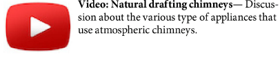
✓ Recognize soot near the draft diverter, barometric damper, or burner of a combustion appliance as a sign that the appliance produces CO and spills combustion gases.
✓ Recognize that rust in a chimney or vent connector may also indicate spillage.
✓ Look for leaks, disconnections, and blockages in the venting system.
✓ Specify that workers seal all accessible return-duct leaks near combustion furnaces.
✓ Verify that the home has a working CO alarm. If the home has no working smoke alarm in addition to no CO alarm, install a combination CO-smoke alarm, or separate CO and smoke alarms. See also "Smoke and Carbon Monoxide (CO) Alarms" on page 26.
✓ Inspect gas ovens and range burners for flame stability and test them for carbon monoxide. See "Gas Range and Oven Safety" on page 29.
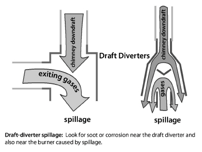
Natural gas and propane piping systems may leak at their joints and fittings. Find gas leaks with an electronic combustible-gas detector, also called a gas sniffer. A gas sniffer finds significant gas leaks if used correctly.
✓ Sniff all valves and joints with the gas sniffer.
✓ Accurately locate leaks using a noncorrosive bubbling liquid, designed for finding gas leaks.
✓ Repair all gas leaks or label them for a gas service person to repair.
✓ Replace kinked, cracked, or corroded flexible gas connectors.
✓ Replace flexible gas lines manufactured before 1973. The line’s manufacture date is stamped on a date ring attached to the flexible gas line or on the body of the hex nut. If a date ring isn’t present and you believe the gas line predates 1973, then replace the flexible gas line.
8.2.3 Carbon Monoxide (CO) Testing
CO testing is essential for evaluating the safety of combustion and venting. Measure CO in the flue gas of every combustion appliance you inspect and service. Measure CO in ambient air in both the home and CAZ as part of inspection and testing of combustion appliances. We strongly recommend using a full-featured electronic combustion analyzer for flue-gas analysis during this essential combustion safety testing. See “Critical Combustion-Testing Parameters” on page 273.
Vent Testing for CO
Testing for CO in the appliance vent is a part of combustion testing that happens under worst-case conditions. If the undiluted combustion byproducts exceed the following CO limits, the appliance fails the CO test under current BPI standards.
• Vented space heaters and water heaters: 100 ppm as measured or 200 ppm air-free.
• Furnaces or boilers: 200 ppm as measured or 400 ppm air-free.
• Oven and range burners: 225 ppm as measured. See "Gas Range and Oven Safety" on page 29.
Ambient Air Monitoring for CO
The DOE SWS require CO monitoring during combustion testing to ensure that CO in the combustion appliance zone (CAZ) doesn’t exceed dangerous levels.
✓ If ambient CO level in the CAZ exceeds 70 ppm, stop testing for your own safety. Communicate the situation clearly to the client, immediately evacuate the home, and contact appropriate personnel.
✓ If ambient CO level in the CAZ exceeds 35 ppm, but is less than 70 ppm, communicate the issue clearly and immediately to the customer and suggest appropriate solutions. Exam appliances for signs of damage, misuse, improper repairs, and lack of maintenance.
✓ Ventilate the CAZ thoroughly before resuming combustion testing.
✓ Investigate indoor CO levels (which are greater than outdoor ambient levels) to determine their cause. See "Causes of Carbon Monoxide (CO)" on page 25.
8.2.4 Worst-Case CAZ Depressurization Testing
|
SWS Detail: 2.0103.1 Combustion Worker Safety, 2.0201.1 Combustion Appliance Zone (CAZ) Testing, 2.0201.2 Combustion Safety - Make-up Air, 2.0201.3 Vented Combustion Appliance Safety Testing |
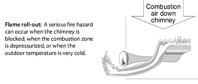
CAZ depressurization is the leading cause of backdrafting and flame roll-out in furnaces and water heaters that vent into naturally drafting chimneys and venting systems.
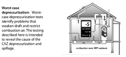
Worst-case depressurization testing uses the home’s exhaust fans, air handler, and chimneys to create worst-case depressurization in the CAZ. During this worst-case testing, you measure the CAZ pressure difference with reference to (WRT) outdoors and test for spillage.
Worst-case conditions do occur, and venting systems must exhaust combustion byproducts even under these extreme conditions. Worst-case vent testing exposes whether or not the venting system exhausts the combustion gases when the combustion-zone pressure is as negative as you can make it. A digital manometer is the best tool for accurate and reliable readings of combustion-zone depressurization.
Take all necessary steps to reduce CAZ depressurization and minimize combustion spillage, based on your tests.
Worst-Case CAZ Depressurization Test
Follow the steps below to find the worst-case depressurization level in the combustion appliance zone (CAZ).
1. Turn off or set to pilot all vented combustion appliances.
2. Close all exterior doors, windows, and fireplace damper(s). Open all interior doors, including closet doors.
3. Set all combustion appliances to the pilot setting or turn them off at the service disconnect. Don’t fire the burner of the combustion appliance yet.
4. Remove furnace filter if it’s dirty. Leave the dirty filter out for the test or replace it with a new filter. Be sure the filter slot is covered for the test.
5. Record the baseline pressure of the CAZ with reference to outdoors.
6. Turn on the clothes dryer and exhaust fans. (Clean clothes dryer filter and empty the dryer first.)
7. Open doors to negative-pressure zones (rooms with exhaust fans) and close doors to positive zones (bedrooms without returns). Use smoke or a manometer to verify room pressures if necessary.
8. Open and close the CAZ door. Record the most negative pressure and note CAZ door position.
9. Turn on the furnace air handler. Leave it on if the CAZ pressure goes more negative. If it goes more positive, turn off the air handler and proceed to step 10.
10. Open and close the CAZ door. Record the most negative pressure, and note CAZ door position.
11. Calculate the net difference between the worst depressurization found from either #6 or #8 and the baseline pressure from #3. This is the worst-case depressurization.
12. Refer to the “Maximum CAZ Depressurization” on page 548.
13. Specify improvement if the CAZ exceeds the measured worst-case depressurization limit. See "Evaluating Combustion Air at Worst-Case" on page 263.
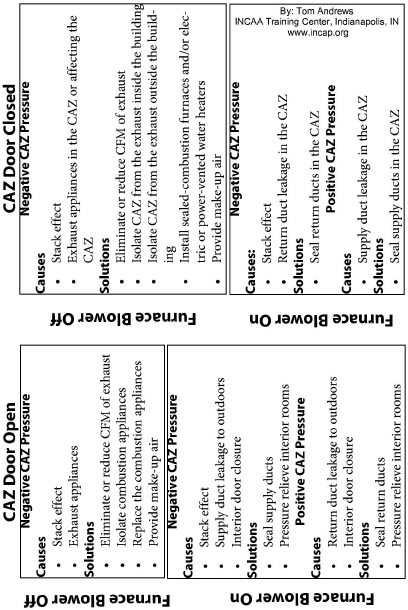
Analyzing CAZ Depressurization
Analyze the negative and positive pressures you measure in the CAZ to find workable solutions, using the troubleshooting table here.
Next, verify that the combustion gases don’t spill or contain excessive CO at worst-case depressurization. Test each appliance in turn for spillage and CO as described below.
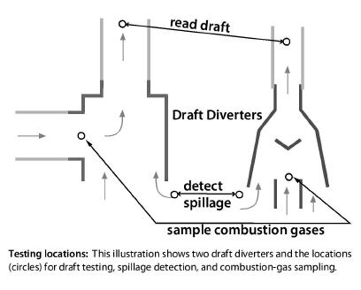
1. Check for flue-gas flow in the venting system. Feel the vent connector for heat. The vent connector should start warming within 5 seconds if it establishes flue-gas flow. If the vent connector remains cold, stop the test and investigate.
2. Detect spillage at the draft diverter of each combustion appliance in one of these ways.
a. Smoke from a smoke generator is repelled by spillage at the draft diverter.
b. A mirror fogs from spillage at the draft diverter
3. If spillage in one or more appliances continues at worst-case depressurization for 2 minutes or more, take action to correct the problem.
4. Measure CO in the undiluted flue gases of each vented space heater or water heater after 2 minutes of operation at worst-case depressurization. If CO in undiluted flue gases is more than 100 ppm as measured or 200 ppm air-free measurement, take action to reduce CO level.
5. Measure CO in the undiluted flue gases of each furnace or boiler after 2 minutes of operation at worst-case depressurization. If CO in undiluted flue gases is more than 200 ppm as measured or 400 ppm air-free measurement, take action to reduce CO level.
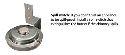
Spillage and draft: Spillage and draft are two indications of whether the combustion gases are exiting the building as they should. In this guide, we focus on spillage because we’re trying to avoid spillage, and we can detect it easily.
Positive draft indicates spillage, but not as reliably as checking for spillage itself. Evaluate spillage, unless you understand draft and know how to measure it.
8.2.5 Evaluating Combustion Air at Worst-Case
|
SWS Detail: 2.0203.1 Combustion Air for Natural Draft Appliances |
Combustion appliances need an air supply to support combustion and to balance the draft in natural-draft chimneys. In most buildings, combustion air comes through the building’s air leaks.
If workers seal the building tightly, they may reduce combustion air to a level that causes combustion problems or that allows depressurization. The worst-case testing procedure exposes most of these problems. This section tells how to evaluate combustion air during the worst-case depressurization test and by using a rule of thumb.
Evaluating the CAZ Volume
In the average building with more than 0.40 natural air changes per hour (ACHn), the combustion appliance zone or CAZ should contain more than 50 cubic feet of volume for each 1000 BTUH of combustion-appliance input. However, a smaller volume may provide adequate combustion air and a larger volume may not depending on the airtightness of the CAZ.
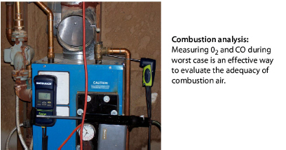
Evaluating Combustion Air by Flue-Gas Analysis
During worst-case testing, use a combustion analyzer to measure both CO and oxygen (O2). See “Critical Combustion-Testing Parameters” on page 273.
The O2 is an indicator of excess combustion air, and high CO may be an indicator of insufficient combustion air.
1. Sample undiluted flue gases as they leave the appliance’s heat exchanger during worst-case conditions.
2. If the O2 reading from the combustion analyzer is more than 5% with a natural-draft burner or more than 3% with a power burner or well adjusted and maintained barometric draft control, combustion air is probably adequate if CO is minimal.
3. If the O2 reading from the combustion analyzer is less than the above O2 values, this indicates that combustion air is inadequate or that the appliance is over-fired. We would expect significant CO to accompany such low O2 readings.
4. If O2 is too low, measure fuel input to verify that the firing rate is at or below the manufacturer’s BTUH specifications for input.
5. If O2 is too low at the correct firing rate, open a door or a window connected to the CAZ. If opening the CAZ door, a nearby window, an exterior door, or any combination of these increases the O2 reading and decreases CO, then consider the options specified in “Combustion-Air-Related Solutions” on page 268.
8.2.6 Mitigating CAZ Depressurization and Spillage
If you find problems with CAZ depressurization or spillage, consider the improvements discussed next to solve these problems.
If the appliance spills or shows inadequate draft, open a window, exterior door, or interior door to observe whether the additional combustion airflow through that opening stops the spillage.
1. If this additional air stops spillage, the problem is usually depressurization.
2. If this additional air doesn’t stop the spillage, inspect the chimney. The chimney may be obstructed, undersized, oversized, or leaky.
Improvements to Mitigate CAZ Depressurization
This list of improvements may solve spillage problems detected during the previous tests on a forced air heating system.
✓ Seal all return-duct leaks in the CAZ or near the furnace.
✓ Isolate combustion appliances from exhaust fans, clothes dryers, and return registers by air sealing between the CAZ and zones containing these depressurizing devices as described on page 268.
✓ Provide make-up air for dryers and exhaust fans.
✓ Reduce the CFM of exhaust appliances.
|
Problem |
Possible Solutions |
|---|---|
|
Spills immediately and continuously |
Remove chimney blockage, seal chimney air leaks, or provide additional combustion air as necessary. |
|
Exhaust fans cause spillage |
Provide make-up or combustion air if opening a door or window to outdoors improves draft during testing. |
|
Blower activation causes spillage |
Seal return leaks in the furnace and in nearby return ducts. Isolate the furnace from nearby return registers. |
Chimney Improvements to Mitigate Spillage Problems
Suggest the following chimney improvements to mitigate spillage problems, detected during the previous testing.
• Remove chimney obstructions.
• Repair disconnections or leaks at joints and where the vent connector joins a masonry chimney.
• Measure the size of the vent connector and chimney and compare to vent-sizing information listed in Chapter 13 of the National Fuel Gas Code (NFPA 54). A vent connector or chimney liner that is either too large or too small can cause spillage.
• If wind causes spillage, install a wind-dampening chimney cap.
• If heat and moisture have deteriorated the masonry chimney, install a new chimney liner.
• Increase the pitch of horizontal sections of vent, if the pitch is less than 1/4 inch per foot.
• Increase the vertical rise of the vent connector, directly off the appliance vent fitting.
• Replace a single-wall vent connector with a double-wall vent connector.
Fixing Persistent Depressurization and Spillage Problems
Sometimes buildings and their combustion appliances don’t respond to the possible solutions listed previously. For persistent depressurization, spillage, and make-up air consider the following solutions.
• Replace open combustion appliances with sealed-combustion appliances.
• For an orphaned water heater either reline the chimney with a correctly sized chimney liner or replace gas or oil-fired water heaters with electric water heaters.
• If opening the CAZ door reduces worst-case CAZ depressurization, consider providing a vent between the CAZ and surrounding zones.
8.2.7 Combustion-Air-Related Solutions
If combustion air is inadequate after trying the solutions in the previous sections, consider replacing open-combustion appliances with sealed-combustion appliances. The options discussed here have a risk of failure because of the unknowns with installing supplemental combustion air and isolating CAZs from the remainder of the building. Sealed-combustion is the ultimate answer to the problems of combustion air, depressurization, and spillage.
Installing Supplemental Combustion Air
Combustion-air vents should be no less than 3 inches in their smallest dimension. A vent with a louver or grille has a net free area (NFA) that is smaller than actual vent area because NFA accounts for the blocking effect of louvers and grilles. Metal grilles and louvers provide about 75% of their area as net-free area while wood louvers provide only about 25%.
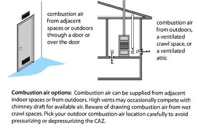
The table shown here gives sizing guidelines for combustion air openings. If testing indicates the need for supplemental combustion air, install openings to one of these places.
• Another indoor space
• A ventilated intermediate zone, such as a ventilated attic or ventilated crawl space
• From outdoors into an isolated CAZ. See below.
• From outdoors to the appliance by replacing natural-draft combustion appliances with sealed-combustion (direct-vent) appliances.
After installing supplemental combustion air, repeat the worst-case testing to verify that the combustion air problem is solved and that the combustion is safe.
|
Location |
Dimensions |
|---|---|
|
Two direct openings to adjacent indoor space |
Minimum area each: 100 in2 1 in2 per 1000 BTUH each Combined room volumes must be ≥ 50 ft3/1000 BTUH |
|
Two direct openings or vertical ducts to outdoors |
Each vent should have 1 in2 for each 4000 BTUH |
|
Two horizontal ducts to outdoors or ventilated intermediate zone |
Each vent should have 1 in2 for each 2000 BTUH |
|
Single direct or ducted vent to outdoors or ventilated intermediate zone |
Single vent should have 1 in2 for each 3000 BTUH |
|
From the National Fuel Gas Code 2009 (NFPA 54) |
|
Zone Isolation for Natural-Draft Vented Appliances
If replacing natural-draft appliances with sealed-combustion isn’t an option, isolating the CAZ improves the safety of natural-draft vented appliances in some cases. The CAZ is isolated if it receives combustion air only from outdoors or a ventilated intermediate zone. Inspect the CAZ for connections with the home’s main zone and seal all connections.
1. Seal all connections between the isolated CAZ and the home. Examples include joist spaces, transfer grills, leaky doors, and holes for ducts or pipes.
2. Measure a base pressure from the CAZ to outdoors.
3. Set-up house in worst case, and verify that the set-up doesn’t affect the CAZ pressure.
4. Measure CO and O2 at worst-case and evaluate combustion air as described in “Evaluating Combustion Air by Flue-Gas Analysis” on page 264.
5. If the CAZ-to-outdoors pressure changed during worst-case, continue to air-seal the CAZ, and retest as described in steps #2 and #3.
6. If you can’t air-seal the CAZ adequately to isolate the zone, solve worst-case depressurization and spillage problems as described in “Evaluating Combustion Air at Worst-Case” on page 263.
7. If the zone isolation fails, replace natural-draft appliances with sealed-combustion appliances.