8.7 Oil Burner Safety and Efficiency Service
These procedures apply to oil-fired furnaces, boilers, and water heaters.
Oil burners require annual maintenance to maintain acceptable safety and combustion efficiency. Use combustion analysis to evaluate the oil burner and to guide maintenance and adjustment. Use other test equipment as discussed to measure other essential operating parameters and to make adjustments as necessary.
8.7.1 Oil Burner Testing and Adjustment
|
SWS Detail: 5.3003.2 Combustion Analysis of Oil-Fired Appliances |
Unless the oil-fired heating unit is very dirty or disabled, technicians should do combustion testing and adjust the burner for safe and efficient operation.
Combustion Testing and Adjustment
Combustion testing is essential to understanding the current oil burner performance and potential for improvement.
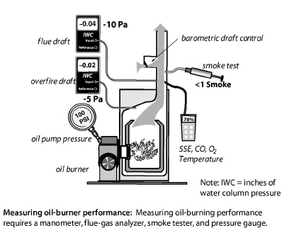
✓ Sample the undiluted flue gases with a smoke tester, after reading the smoke tester instructions. Compare the smoke smudge left by the gases on the filter paper with the manufacturer’s smoke-spot scale to find the smoke number.
✓ If the smoke number is higher than 3, take steps to reduce smoke before sampling the gases with a combustion analyzer to prevent the smoke from fouling the analyzer.
✓ Sample undiluted flue gases between the barometric draft control and the appliance. Analyze the flue gas for O2, flue-gas temperature, CO, and steady-state efficiency (SSE).
✓ Measure the draft over the fire inside the firebox (overfire draft) through a plug in the heating unit.
✓ A flue gas temperature more than 450° F indicates that a clean heating unit is oversized. Exceptions: steam boilers and boilers with tankless coils. If the nozzle is oversized, replace the burner nozzle after selecting the correct nozzle size, spray angle, and spray pattern.
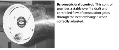
✓ Adjust the barometric damper for a negative overfire draft of –0.020 IWC or –5 pascals at a test plug in the heating unit.
✓ Adjust the air shutter to achieve the oxygen and smoke values, specified in Table 8-6 on page 297.
✓ Adjust oxygen, flue-gas temperature, CO, and smoke number to match manufacturer’s specifications or specifications given here. Smoke number should be near zero on all modern oil-fired equipment.
Other Efficiency Testing and Adjustment
✓ Adjust the gap between electrodes and their angle for proper alignment.
✓ Measure the control-circuit amperage. Adjust the thermostat’s heat anticipator to match the amperage, or read the thermostat manufacturer’s instructions for adjusting cycle length.
✓ Measure the oil-pump pressure, and adjust it to manufacturer’s specifications if necessary.
✓ Measure the transformer voltage, and adjust it to manufacturer’s specifications if necessary.
✓ Adjust the airflow or the water flow to reduce high flue-gas temperature if possible, but don’t reduce flue-gas temperature below 350°F.
8.7.2 Oil Burner Inspection and Maintenance
See “HVAC-System Commissioning” on page 252. See “HVAC-System Education” on page 253.
Use visual inspection and combustion testing to evaluate oil burner operation. An oil burner that passes visual inspection and complies with the specifications on page 297 may need no maintenance. Persistent unsatisfactory test results may indicate the need to replace the burner or the entire oil-fired heating unit.
Safety Inspection, Testing, and Adjustment
✓ Inspect burner and appliance for signs of soot, overheating, fire hazards, corrosion, or wiring problems.
✓ Inspect heat exchanger and combustion chamber for cracks, corrosion, or soot buildup.
✓ If the unit smells excessively of oil, test for oil leaks and repair the leaks.
✓ Time the flame sensor control or stack control to verify that the burner shuts off, within either 45 seconds or a time specified by the manufacturer, when the cad cell is blocked from seeing the flame.
✓ Measure the high limit shut-off temperature and adjust or replace the high limit control if the shut-off temperature is more than 200° F for furnaces, or 220° F for hot-water boilers.
Oil Burner Maintenance
After evaluating the oil burner’s operation, specify some or all of these maintenance tasks as necessary, to optimize safety and efficiency.
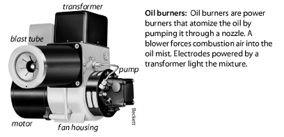
✓ Clean the burner’s blower wheel.
✓ Clean dust, dirt, and grease from the burner assembly.
✓ Replace oil filter(s) and nozzle.
✓ Clean or replace air filter.
✓ Remove soot from combustion chamber.
✓ Remove soot from heat exchange surfaces.
✓ Adjust gap between electrodes to manufacturer’s specs.
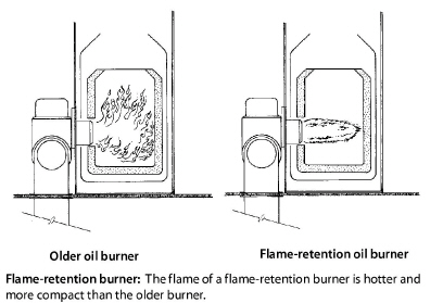
✓ Check if the nozzle and the fire ring of the flame-retention burner is appropriate for the size of the combustion chamber.
✓ Repair the ceramic combustion chamber, or replace it if necessary.
✓ Verify correct flame sensor operation.
After these maintenance procedures, the technician carries out the diagnostic tests described previously to evaluate improvement made by the maintenance procedures and to determine whether more adjustment or maintenance is required.