Home > Chapter 8: Heating and Cooling Systems > 8.13 Ducted Air Distribution
The forced-air system consists of an air handler (furnace, heat pump, air conditioner) with its heat exchanger along with attached ducts. The annual system efficiency of forced-air heating and air-conditioning systems depends on the following issues.
• Duct leakage
• System airflow
• Blower operation
• Balance between supply and return air
• Duct insulation levels
The evaluation and improvement of ducts has a logical sequence of steps.
ü Solve the airflow problems because a contractor might have to replace ducts or install additional ducts.
ü Determine whether the ducts are located inside the thermal boundary or outside it.
ü Evaluate the ducts’ air leakage and decide whether duct-sealing is important and if so, find and seal the duct leaks.
ü If supply ducts are outside the thermal boundary or if condensation is an air-conditioning problem, insulate the ducts.
You don’t need test instruments to discover dirty blowers or disconnected branch ducts. Find these problems before measuring duct airflow, troubleshooting the ducts, or sealing the ducts. These steps precede airflow measurements.
1. Ask the customer about comfort problems and temperature differences in different rooms of the home.
2. Based on the customers comments, look for disconnected ducts, restricted ducts, and other obvious problems.
3. Inspect the filter(s), blower, and indoor coil for dirt. Clean them if necessary. If the indoor coil isn’t easily visible, a dirty blower means that the coil is probably also dirty.
4. Look for dirty or damaged supply and return grilles that restrict airflow. Clean and repair them.
5. Look for closed registers or closed balancing dampers that could be restricting airflow to uncomfortable rooms.
6. Notice moisture problems like mold and mildew. Moisture sources, like a wet crawl space, can overpower air conditioners by introducing more moisture into the air than the air conditioner can remove.
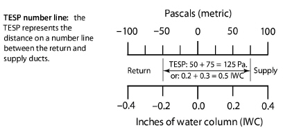
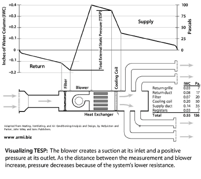
The blower creates the duct pressure, which is measured in inches of water column (IWC) or pascals. The return static pressure is negative and the supply static pressure is positive. Total external static pressure (TESP) is the sum of the absolute values of the supply and return static pressures. Absolute value means that you ignore the positive or negative signs when adding supply static pressure and return static pressure to get TESP. This addition represents the distance on a number line as shown in the illustration here.
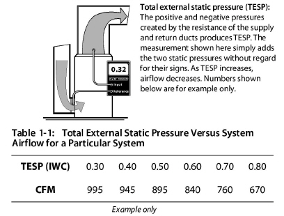
TESP gives a rough indicator of whether airflow is adequate. The greater the TESP, the less the airflow. The supply and return static pressures by themselves can indicate whether the supply or the return or both sides are restricted. For example, if the supply static pressure is 0.10 IWC (25 pascals) and the return static pressure is –0.5 IWC (-125 pascals), you can assume that most of the airflow problems are due to a restricted or undersized return. The TESP give a rough estimate of airflow if the manufacturer’s graph or table for static pressure versus airflow is available.
1. Attach two static pressure probes to tubes leading to the two ports of the manometer. Attach the high-side port to the probe inserted downstream of the air handler in the supply duct. The other tube goes upstream of the air handler in the return duct. The manometer adds the supply and return static pressures to measure TESP.
2. Consult manufacturer’s literature for a table of TESP versus airflow for the blower or the air handler. Find airflow for the TESP measured in Step 1.
3. Measure pressure on each side of the air handler to obtain both supply and return static pressures separately. This test helps to locate the main problems as related to either the supply or the return.
Air handlers deliver their airflow at TESPs ranging from 0.30 IWC (75 Pascals) to 1.0 IWC (250 Pascals) as found in the field. Manufacturers maximum recommended static pressure is usually a maximum 0.50 IWC (125 pascals) for standard air handlers. TESPs greater than 0.50 IWC indicate inadequate airflow in standard residential forced-air systems.
The popularity of pleated filters, electrostatic filters, and high-static high-efficiency evaporator coils, prompted manufacturers to introduce premium air handlers that can deliver adequate airflow at a TESPs of greater than 0.50 IWC (125 pascals). Premium residential air handlers can provide adequate airflow with TESPs of up to 0.90 IWC (225 pascals) because of their more powerful blowers and variable-speed blowers. TESPs greater than 0.90 IWC indicate the possibility of inadequate airflow in these premium residential forced-air systems.
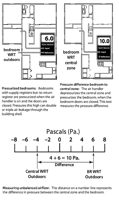
Closing interior doors often separates supply registers from return registers in homes with central returns. A bedroom door with no return register and a closed door restricts the bedroom air from returning to the air handler. This restriction pressurizes bedrooms and depressurizes the central areas near return registers. These pressures can drive air leakage through the building shell, create moisture problems, and bring pollutants in from the crawl space, garage, or CAZ.
The following test uses only the air handler and a digital manometer to evaluate whether the supply air can flow back to the return registers relatively unobstructed. Activate the air handler and close interior doors.
1. Measure the pressure difference between the home’s central living area and the outdoors with a digital manometer.
2. Measure the bedrooms’ pressure difference with reference to outdoors.
If the sum of these two measurements is more than 3.0 pascals with the air handler operating, pressure relief is desirable. Like TESP, disregard the positive or negative signs, and add the absolute values.
• Or, you can measure the pressure difference between the central zone and the bedroom as shown in the next illustration.
To estimate the amount of pressure relief needed, slowly open the bedroom door until the pressure difference drops below 1 pascal.
Estimate the surface area of that door opening. This is the area of the permanent opening required to provide pressure relief. Pressure relief may include undercutting the door or installing transfer grilles or jumper ducts.
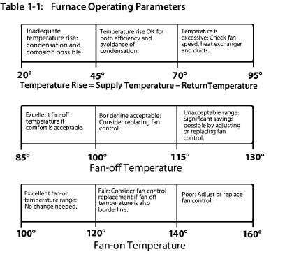
The effectiveness of a furnace depends on its temperature rise, fan-control temperatures, and flue-gas temperature. For efficiency, you want a low temperature rise. However, you must maintain a minimum flue-gas temperature to prevent corrosion in the venting of 70+ and 80+ AFUE furnaces. Apply the following furnace-operation standards to maximize the heating system’s seasonal efficiency and safety.
ü Perform a combustion analysis as described in “Gas Burner Safety & Efficiency Service” on page 266.
ü Check temperature rise after 5 minutes of operation. Refer to manufacturer’s nameplate for acceptable temperature rise (supply temperature minus return temperature). The temperature rise should be between 40°F and 70°F with the lower end of this scale being preferable for energy efficiency.
ü Verify that the fan-off temperature is between 95° and 105° F. The lower end of this scale is preferable for maximum efficiency.
ü Verify that the fan-on temperature is 120–140° F. The lower the better.
ü With time-activated fan controls, verify that the fan is switched on within two minutes of burner ignition and is switched off within 2.5 minutes of the end of the combustion cycle.
ü Verify that the high limit controller shuts the burner off before the furnace temperature reaches 200°F.
ü Verify that there is a strong noticeable airflow from all supply registers.
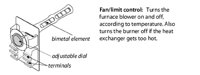
ü Adjust fan control to conform to these standards, or replace the fan control if adjustment fails. Some fan controls aren’t adjustable.
ü Adjust the high limit control to conform to the above standards, or replace the high limit control.
ü All forced-air heating systems must deliver supply air and collect return air only from inside the intentionally heated portion of the house. Taking return air from an un-heated area of the house such as an unconditioned basement or a crawl space isn’t acceptable.
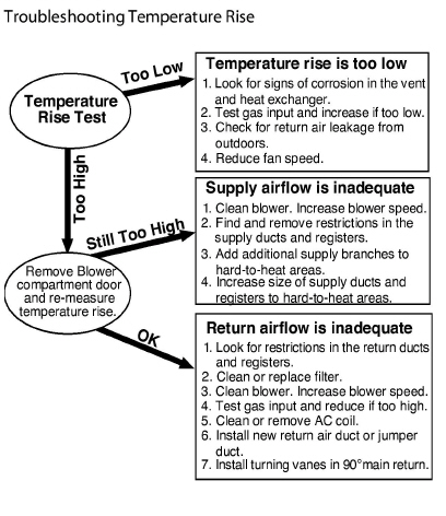
Inadequate airflow is a common cause of comfort complaints. When the air handler is on there should be a strong flow of air out of each supply register. Low register airflow may mean that a branch duct is blocked or separated, or that return air from the room to the air handler isn’t sufficient. When low airflow is a problem, consider specifying the following improvements as appropriate from your inspection.
ü Clean or change filter. Select a less restrictive filter if you need to reduce static pressure substantially.
ü Clean air handler’s blower.
ü Clean air-conditioning or heat pump coil.
ü Clean the air-conditioning coil. If the blower is dirty, the coil is probably also dirty.
ü Increase blower speed.
ü Make sure that balancing dampers to rooms that need more airflow are wide open.
ü Lubricate blower motor, and check tension on drive belt.
Consider specifying the following duct changes to increase system airflow and reduce the imbalance between supply and return.
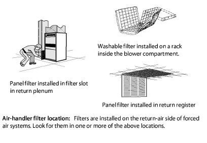
ü Modify the filter installation to allow easier filter changing, if filter changing is currently difficult.
ü Install a slanted filter bracket assembly or a enlarged filter fitting to accommodate a larger filter with more surface area and less static-pressure drop than the existing filter.
ü Remove obstructions to registers and ducts such as rugs, furniture, and objects placed inside ducts, such as children’s toys and water pans for humidification.
ü Remove kinks from flex duct, and replace collapsed flex duct and fiberglass duct board.
ü Remove excessive lengths of slacking flex duct, and stretch the duct to enhance airflow.
ü Perform a Manual D sizing evaluation to evaluate whether to replace branch ducts that are too small.
ü Install additional supply ducts and return ducts as needed to provide heated air throughout the building, especially in additions to the building.
ü Undercut bedroom doors, especially in homes without return registers in bedrooms.
ü Repair or replace bent, damaged, or restricted registers. Install low-resistance registers and grilles.