Gas burners should be inspected and maintained during a service call. These following specifications apply to gas furnaces, boilers, water heaters, and space heaters.
Perform the following procedures at steady-state efficiency (SSE) to verify a furnace’s correct operation.
• Perform a combustion test using a electronic flue-gas analyzer. Recommended flue-gas temperature depends on the type of furnace and is listed in the table titled, “Combustion Standards for Gas Furnaces and Boilers” on page 250.
• Measure temperature rise (supply minus return temperatures). Temperature rise should be within the manufacturer’s specifications for a furnace or boiler: between 30° and 70°.
• If O2 is high, or the estimated output from the table is low, increase gas pressure to 6% O2 if possible as long as you don’t create CO.
• Increase gas pressure if needed to increase temperature rise and flue-gas temperature.
If you know the airflow through the furnace from measurements described in “Ducted Air Distribution” on page 299, you can use the table, “Gas Furnace Output Table” on page 484, to check whether output is approximately what the manufacturer intended. Dividing this output by measured input as described above gives you another check on the steady-state efficiency.
Perform the following inspection procedures on all gas-fired furnaces, boilers, water heaters, and space heaters, as necessary.
ü Look for soot, melted wire insulation, and rust in the burner and manifold inside and outside the burner compartment. These signs indicate flame roll-out, combustion gas spillage, CO, and incomplete combustion.
ü Inspect the burners for dust, debris, misalignment, flame-impingement, and other flame-interference problems. Clean, vacuum, and adjust as needed.
ü Inspect the heat exchanger for cracks, holes, or leaks.
ü Verify that furnaces and boilers have dedicated circuits with fused safety shutoffs near the appliance. Verify that all 120-volt wiring connections are enclosed in covered electrical boxes.
ü Verify that pilot is burning (if equipped) and that main burner ignition is satisfactory.
ü Check venting system for proper diameter and pitch. See page 281.
ü Check venting system for obstructions, blockages, or leaks.
ü Observe flame characteristics. Flames should be blue and well shaped. If flames are white or yellow, the burner may suffer from faulty combustion.
The goal of these measures is to reduce carbon monoxide (CO), stabilize flame, and verify the operation of safety controls.
ü Do an electronic combustion analysis and note the oxygen, CO, and flue-gas temperature.
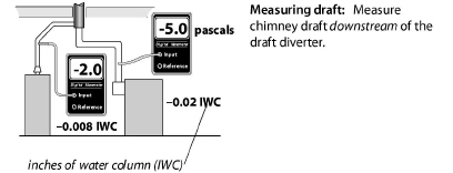
ü Test for spillage or measure draft. Take action to improve the draft if it is inadequate because of improper venting, obstructed chimney, leaky chimney, or depressurization. See page 242.
ü If you measure CO and the measured oxygen level is low, open a window while observing CO level on the meter to see if CO is reduced by increasing the available combustion air through the open window. See page 294.
ü Adjust gas input if combustion testing indicates over-firing or under-firing.
ü For programmable thermostats, read the manufacturer’s instructions about how to control cycle length. These instructions may be printed inside the thermostat.
Clean and adjust the burner if any of these conditions exists.
• CO is greater than 100 ppm as measured or 200 ppm air-free measurement for space heaters and water heaters and 200 ppm as measured or 400 air-free for furnaces or boilers.
• Visual indicators of soot or flame roll-out exist.
• Burners are visibly dirty.
• Measured draft is inadequate. See page 281.
• The appliance has not been serviced for two years or more.
Gas-burner and gas-venting maintenance should include the following measures.
ü Remove causes of CO and soot, such as over-firing, closed primary air intake, flame impingement, and lack of combustion air.
ü Remove dirt, rust, and other debris that may be interfering with the burners. Clean the heat exchanger if there are signs of soot around the burner compartment.
ü Seal leaks in vent connectors and chimneys.