9.3 Fan and Duct Specifications
This section covers fan and duct specifications for both local ventilation and whole-building ventilation. Duct sizing, materials, and installation determine whether airflow meets the design amount (CFM). Most existing exhaust fans and ventilation systems don’t achieve their design airflow because of installation flaws.
Continuous ventilation is highly recommended because it simplifies design and control. Continuous ventilation also minimizes depressurization by allowing selection of the minimum-sized fan. Exhaust fans, installed as part of weatherization work, must vent to outdoors and should include the following features.
1. Rated for continuous operation if the fan operates continuously.
2. A weatherproof termination fitting.
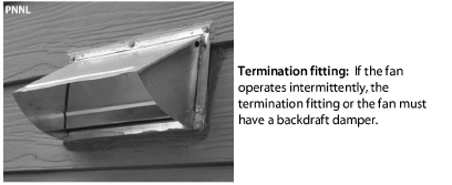
3. Unless the fan operates continuously, the fan housing or termination fitting should house a backdraft damper.
4. Noise rating and ventilation efficacy as specified in the table. (Exception: Inline fans installed remotely.)
|
Fan |
Noise Rating (sones) |
|---|---|
|
Whole-dwelling fans |
1 sone or less |
|
Continuous Local Exhaust Fan |
1 sone or less |
|
Intermittent local ventilation |
3 sones or less |
Fan Installation
Observe these procedures when installing ventilation fans.
✓ Install the fan or ventilator as close as possible to its termination.
✓ Orient the fan or ventilator housing so that the exit fittings face toward their termination fittings.
✓ Remove an integral backdraft damper if the fan operates continuously.
✓ Be careful not to inhibit the back-draft-damper operation by installing screws that interfere with the damper’s movement or by damaging the damper housing.
✓ Repair or replace the backdraft damper on an existing fan, if the damper doesn’t open and close freely.
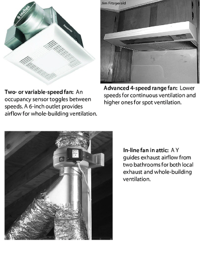
✓ Install in-line fans and multi-port ventilators in remote areas such as attics and crawl spaces and connect the fans to intake grilles in rooms.
✓ Isolate in-line fans and multi-port ventilators from framing to minimize noise.
✓ Measure the fan airflow to verify compliance with ASHRAE 62.2–2016.
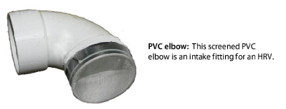
Termination fittings for intake and exhaust ducts must exclude pests and water. Termination fittings must comply with these specifications.
✓ Termination fitting must direct water away from its opening.
✓ Flash or weather-seal termination fittings.
✓ Termination fittings must have insect screens over the openings.
✓ Screens and grilles should be sized not less than 1/4 inch and not more than 1/2 inch.
✓ The termination-fitting collar must be the same diameter as the exhaust or intake fitting on the fan.
✓ If the fan has no backdraft damper and the fan operates intermittently, install a termination fitting with a backdraft damper, to operate in the direction of airflow.
✓ Fasteners must not interfere with backdraft-damper operation.
Locating Termination Fittings
Locate termination fittings using these specifications.
✓ At least 6 inches above grade
✓ At least 10 feet from another fan termination
✓ Above local snow or flood line
✓ At least18 inches above a sloped asphalt based roof
✓ Never on a flat roof
✓ As required by local building authority
✓ Exhaust terminations must be at least 3 feet away from an operable window, an exterior door, or the property line.
Fans often fail to deliver their rated airflow capacity. Bends, un-straight flex duct, dirty grilles, and backdraft dampers can reduce design airflow by 50% or more.
Follow the manufacturer’s specifications for duct sizing. If you follow the sizing in this table, you may achieve the fan’s rated airflow for short duct runs with a maximum of two elbows.
For more detailed duct-sizing recommendations, see“ASHRAE 62.2 Duct Sizing” on page 517.
|
Desired CFM |
25 |
50 |
75 |
100 |
150 |
200 |
|---|---|---|---|---|---|---|
|
Rigid |
4 |
5 |
6 |
7 |
8 |
9 |
|
Flex duct |
5 |
6 |
7 |
8 |
9 |
10 |
|
Friction rate = 0.05; maximum equivalent length =100 feet |
||||||
9.3.4 Duct Materials and Installation
This sections covers SWS requirements and best practices for installing ventilation ducts connected to exhaust fans, ventilators, and air handlers.
Rigid Duct Installation
Observe these best practices for installing rigid ventilation ducts.
✓ Prefer rigid smooth metal pipe (30 gauge or thicker) or plastic pipe (Schedule 30 or thicker) for ventilation duct.
✓ Limit elbows to a maximum of two per duct run.
✓ Use three equally spaced sheet-metal screws to fasten sections of round metal duct together.
✓ Join rigid duct sections so the edge of male end of a duct section isn’t opposing airflow.
✓ Follow manufacturer’s instructions to join other types of rigid ducts together.
✓ Seal all rigid-duct joints and seams with mastic, mastic and webbing, or metal tape, labeled UL181B or UL181B-M. See Sealing Duct Leaks.
✓ Support metal ducts with at least 1/2-inch, 18 gage strapping or at least 12-gage galvanized wire, not less than 10 feet apart.
✓ Insulate metal ducts to R-8 to prevent condensation if they travel through unconditioned spaces. See Duct Insulation.
✓ Fasten PVC exhaust ducts together with approved PVC cement.
Flexible Duct Installation
If rigid duct is not feasible, flexible duct may be used. Observe these best practices for installing flexible ducts.
✓ Stretch flex duct and support it every 4 feet with a 1.5-inch duct support.
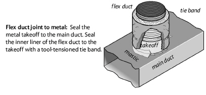
✓ Use tool-tensioned plastic tie bands to join both the inner liner and the outer liner of the flex duct to the rigid duct or a fitting on the fan or termination fitting.
✓ Install a screw to secure the flex duct and tie band to the metal duct between the tie band and the end of the metal duct.
✓ Flexible air duct material must meet UL 181, NFPA 90A/90B, International Mechanical Code, or the Uniform Mechanical Code.