
This chapter discusses ventilation, fans, termination fittings, ducts, and passive vents.
This chapter covers these 4 types of ventilation.
1. Local ventilation
2. Whole-dwelling ventilation
3. Attic and crawl space ventilation
4. Ventilation for cooling
Before installing a mechanical whole-dwelling ventilation system, read “Health and Safety” on page 21 for more information on controlling the sources of moisture and indoor air pollutants.
Controlling pollutants at the source is the highest priority for good indoor air quality. Mechanical ventilation dilutes pollutants. However, ventilation is ineffective against prolific sources of moisture and pollutants. Ask these questions to evaluate pollution sources.
• Do the occupants have symptoms of dwelling-related illnesses? See also "Health and Safety" on page 21.
• Do sources of moisture like ground water, humidifiers, water leaks, or unvented space heaters cause indoor dampness, high relative humidity, or moisture damage? See “Reducing Moisture Problems” on page 31.
• Are there combustion appliances, especially unvented ones, in the living space?
• Do the occupants smoke?
• Are there paints, cleaners, pesticides, gas or other chemicals stored in the home?
10.1.1 Pollution-Control Checklist
Survey the home for pollutants before air-sealing or ventilating the home. Perform the following pollutant-control measures if needed.
✓ Repair roof and plumbing leaks.
✓ Install a ground moisture barrier over bare soil in crawl spaces or dirt-floor basements.
✓ Verify that dryer ducts and exhaust fans move exhaust air to the outdoors.
✓ Verify that combustion-appliance vent systems operate properly.
✓ Move paints, cleaning solvents, and other chemicals out of the conditioned space if possible.
✓ Air-seal between attached garages and a dwelling’s conditioned areas.
✓ Don’t leave un-vented space heaters as a primary heat source.
The dwelling’s occupants are often the source of many home pollutants, such as candles, deodorizers, and pesticides. Educate the residents about minimizing such pollutants in their dwellings.
Note: Ventilation specialists now use the term “dwelling” to describe either a single-family home or multifamily living unit, ASHRAE 62.2–2016 now applies to both single-family and multifamily dwellings.
10.2 ASHRAE Standard 62.2–2016 Ventilation
Most dwellings in North America currently rely on air leakage for ventilation. The American Society of Heating, Refrigerating, and Air Conditioning Engineers (ASHRAE) publishes ventilation standards for dwellings.
Their current standard, ASHRAE 62.2–2016, defines the roles and minimum requirements for mechanical and natural ventilation systems and the building envelope. The roles and requirements intend to provide acceptable indoor air quality in residential buildings.
10.2.1 ASHRAE 62.2–2016 Components
If you air-seal dwellings during weatherization, you may need to install whole-dwelling mechanical ventilation systems under ASHRAE 62.2–2016, which has 3 components.
1. Whole-dwelling ventilation.
2. Local ventilation.
3. Natural infiltration credit.
This ventilation standard allows for natural infiltration (air leakage) to contribute toward the required whole-dwelling ventilation rate for single-family homes and horizontally attached multifamily buildings (but not vertically attached multifamily buildings.
10.2.2 Whole-Dwelling Ventilation Requirement
To comply with ASHRAE 62.2–2016, use either the formula or the table shown here to determine the whole-dwelling ventilation airflow requirement.
You can provide this mechanical airflow in 4 ways.
1. A dedicated exhaust or supply fan running continuously or cycling by automatic control.
2. A bathroom or kitchen exhaust fan running continuously or cycling by automatic control.
3. A central air handler drawing filtered outdoor air into its return.
4. A balanced ventilation system such as a heat-recovery ventilator (HRV) or energy-recovery-ventilator (ERV).
Room Pressure Imbalances
If any room in the building exceeds ±3 pascals pressure with reference to the common area when all interior doors are closed and while the ventilation system is operating, take action to reduce the pressure. Install transfer grilles or jumper ducts as needed to reduce the room to common area pressure difference to less than ±3 pascals. SWS Detail: 6.6201.2 Primary Ventilation Air Flow between Rooms
Option 1: Finding the Airflow Requirement Using the Formula
If you want to install the minimum ventilation capacity, use these 3 steps to follow the formula option.
1. Determine the floor area of the conditioned space of the home in square feet (Afloor).
2. Determine the number of bedrooms (Nbr).
3. Insert these numbers in the formula shown next.
Option 2: Finding the Airflow Requirement Using the Table
Note: If you know the number of occupants, compare the number of occupants with the number of bedrooms plus 1 and use the higher of those two values.
You can also determine the required continuous fan airflow under ASHRAE 62.2–2016 using the table shown here.
|
Floor Area (ft2) |
Number of Bedrooms |
||||
|
1 |
2 |
3 |
4 |
5 |
|
|
30 |
38 |
45 |
53 |
60 |
|
|
501-1000 |
45 |
53 |
60 |
68 |
75 |
|
1001-1500 |
60 |
68 |
75 |
83 |
90 |
|
1501-2000 |
75 |
83 |
90 |
98 |
105 |
|
2001-2500 |
90 |
98 |
105 |
113 |
120 |
|
2501-3000 |
105 |
113 |
120 |
128 |
135 |
|
3001-3500 |
120 |
128 |
135 |
143 |
150 |
|
3501-4000 |
135 |
143 |
150 |
158 |
165 |
|
4001-4500 |
150 |
158 |
165 |
173 |
180 |
|
4501-5000 |
165 |
173 |
180 |
188 |
195 |
|
From ASHRAE Standard 62.2-2016 |
|||||
Additional Ventilation Guidance
If the ventilation airflow requirement is less than 15 CFM, ASHRAE 62.2–2016 exempts the mechanical-ventilation requirement.
Residential Energy Dynamics provides a free online tool to help calculate ASHRAE 62.2–2016 ventilation rates.
Refer to the ASHRAE standard for more details, guidance, and exceptions that are beyond the scope of this field guide.
10.2.3 Local Exhaust Ventilation Requirement
There are two options for complying with the local ventilation requirements for kitchens and bathroom: demand-controlled exhaust or continuous exhaust.
1. For demand-controlled exhaust specify a minimum of 100 CFM for the kitchen, and 50 CFM for each bathroom. An operable window reduces a bathroom’s ventilation requirement to 30 CFM.
2. For continuous exhaust specify a minimum of 20 CFM for each bathroom, and 5 ACH for the kitchen (based on volume).
Local Exhaust Deficit
If the existing kitchen or bathroom ventilation doesn’t meet the requirements stated here, you may adjust the whole-dwelling ventilation rate to compensate for the local airflow deficits. Follow these steps to calculate the local-ventilation deficit in CFM that must be added to the whole-dwelling ventilation rate.
1. Determine the total local exhaust ventilation requirement for all kitchens and bathrooms.
2. Measure the delivered airflow of existing kitchen or bathroom exhaust fans using flow hood, flow grid, or other airflow measuring device. Subtract this amount from the total local exhaust ventilation requirement.
3. If the local jurisdiction allows for operable windows to provide for local ventilation, subtract 20 CFM for each kitchen or bathroom that has an operable window.
The result of these steps is the local exhaust ventilation deficit in CFM. Add 1/4 of this deficit to the required whole-dwelling ventilation rate.
ASHRAE 62.2–2016 allows for infiltration to contribute to the dwelling’s ventilation airflow. Infiltration can supply the entire whole-dwelling ventilation requirement for very leaky buildings. For moderately leaky buildings, infiltration may supply some of the building’s ventilation.
Both single-family and multifamily buildings that are horizontally attached (low rise) are eligible for the infiltration credit.
You can determine the amount of the infiltration credit with a blower door test and weather data based on the building’s location. Calculating the infiltration credit without software is complicated. To simplify the calculations, use the RED Calc Free online tool and select “yes” for the “Use the infiltration credit” option.
10.3 Fan and Duct Specifications
This section covers fan and duct specifications for both local ventilation and whole-dwelling ventilation. Duct sizing, materials, and installation determine whether airflow meets the design airflow rate (CFM). Most existing exhaust fans and ventilation systems don’t achieve their design airflow because of installation flaws.
We highly recommend continuous ventilation. Continuous ventilation simplifies design and control. Continuous ventilation also minimizes depressurization by allowing selection of the minimum-sized fan.
General Fan and Ventilator Specifications
Exhaust fans, installed as part of weatherization work, must vent to outdoors and should include these features.
✓ Rated for continuous operation if the fan operates continuously.
✓ A weatherproof termination fitting, equipped with a screen, louver, or grille material over exterior termination with an opening size of no less than 1/4-inch and no greater than 1/2-inch.
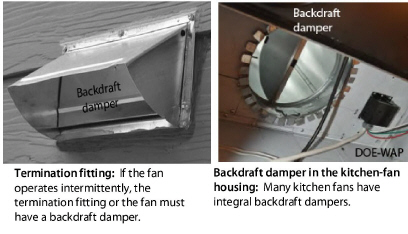
✓ Unless the fan operates continuously, the fan housing or termination fitting should have a backdraft damper that opens in the direction of flow and closes when the fan is off.
✓ Noise rating must be no more than 2 sones.
✓ Ventilation efficacy must be more than or equal to 4 cfm/watt.
✓ The fan must move at least 50 cfm after installation, ducting, and termination are complete.
|
Fan |
Noise Rating (sones) |
|---|---|
|
Whole-dwelling fans |
1 sone or less |
|
Continuous Local Exhaust Fan |
1 sone or less |
|
Intermittent local ventilation |
3 sones or less |
Observe these procedures when installing ventilation fans.
✓ Install the fan or ventilator as close as possible to its termination.
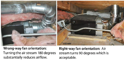
✓ Orient the fan or ventilator housing so that the exit fittings face toward their duct termination fittings, using the shortest duct possible.
✓ Mount fan using mechanical fasteners so that fan housing doesn’t shake, rattle, or vibrate when operating.
✓ Seal gap around fan housing and intake grills with a durable and compatible sealant, appropriate for indoor use.
✓ Remove an integral backdraft damper if the fan operates continuously.
✓ Don’t inhibit back-draft-damper operation by installing screws that interfere with the damper’s movement or by damaging the damper housing.
✓ Repair or replace the backdraft damper on an existing fan, if the damper doesn’t open and close freely.
✓ If fan housing is in unconditioned space, enclose fan housing and insulate it to a minimum of R-8.
✓ Ensure fan and service disconnect switch are accessible for maintenance.
✓ Install in-line fans and multi-port ventilators in remote areas such as attics and crawl spaces and connect the fans to intake grilles in rooms.
✓ Isolate in-line fans and multi-port ventilators from framing to minimize noise.
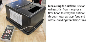
✓ Measure the fan airflow to verify compliance with ASHRAE 62.2–2016.
✓ Install a MERV 6 filter in all ducted supply ventilation systems. See “Evaluating Duct Air Leakage” on page 362.
✓ Select a fan that is rated a maximum of 3 sones at one or more airflow settings greater than or equal to 100 cfm.
✓ The fan must have a minimum efficacy of 2.8 cfm/watt.
✓ The fan must move at least 100 cfm intermittently or 5 kitchen air changes per hour (ACH) continuously after installation, ducting, and termination are complete.
✓ See “Fan Installation” on page 425 for additional requirements.
Inline and Multi-port Fans
✓ Select a fan that: has an electrically commutated motor (ECM) and an efficacy of 3.8 cfm/watt or more.
✓ Seal gaps around intake register boots with compatible sealant.
✓ See “Fan Installation” on page 425 for additional requirements.
10.3.2 Intake and Exhaust Fittings
|
SWS Detail: 6.0101.3 Exterior Intakes; 6.0101.2 Exhaust Terminations |
Termination fittings for intake and exhaust ducts must exclude pests and water. Termination fittings must comply with these specifications.
✓ Termination fittings must terminate outdoors and never in an attic, crawl space, garage, or within 10 feet of an intake fitting.
✓ The hole for termination fitting must leave no more than a 1/4-inch gap around the fitting assembly.
✓ Termination fitting must direct water away from its opening.
✓ Flash or weather-seal termination fittings.
✓ Termination fittings must have insect screens over the openings. Insect screen openings must be between 1/4 and 1/2-inch in size.
✓ The termination-fitting collar must be the same diameter as the exhaust or intake fitting on the fan.
✓ If the fan has no backdraft damper and the fan operates intermittently, install a termination fitting with a backdraft damper, to operate in the direction of airflow.
✓ Don’t inhibit the backdraft damper operation if included in termination fitting — with fasteners, for example,
Locating Termination Fittings
Locate termination fittings using these specifications.
✓ At least 6 inches above grade.
✓ At least 10 feet from another fan termination.
✓ Above local snow or flood line.
✓ At least18 inches above a sloped asphalt based roof.
✓ Comply with local building authority requirements.
✓ Exhaust terminations must be at least 3 feet away from an operable window, an exterior door, or the property line.
Fans often fail to deliver their rated airflow capacity. Bends, un-straight flex duct, dirty grills, and backdraft dampers can reduce design airflow by 50% or more.
If you follow the sizing in this table, you may achieve the fan’s rated airflow for short duct runs with a maximum of two elbows.
For more detailed duct-sizing recommendations, see “ASHRAE 62.2 Duct Sizing” on page 576.
|
Desired CFM |
25 |
50 |
75 |
100 |
150 |
200 |
|---|---|---|---|---|---|---|
|
Rigid |
4 |
5 |
6 |
7 |
8 |
9 |
|
Flex duct |
5 |
6 |
7 |
8 |
9 |
10 |
|
Friction rate = 0.05; maximum equivalent length =100 feet |
||||||
10.3.4 Duct Materials and Installation
|
SWS Detail: 6.0101.1 Ventilation Ducts; 6.0101.2; Exhaust Terminations; 6.0101.3 Exterior Intakes |
This sections covers SWS requirements and best practices for installing ventilation ducts connected to exhaust fans, ventilators, and air handlers.
See also "Sealing Duct Leaks" on page 370.
Rigid Duct Installation
Observe these best practices for installing rigid ventilation ducts.
✓ Prefer rigid smooth metal pipe (30 gauge or thicker) or plastic pipe (Schedule 30 or thicker) for ventilation duct.
✓ Limit elbows to a maximum of two per duct run.
✓ Use three equally spaced sheet-metal screws to fasten sections of round metal duct together.
✓ Join rigid duct sections so the edge of male end of a duct section isn’t opposing airflow.
✓ Follow manufacturer’s instructions to join other types of rigid ducts together.
✓ Seal all rigid-duct joints and seams with mastic, mastic and webbing, or metal tape, labeled UL181B or UL181B-M. See “Sealing Duct Leaks” on page 370.
✓ Support metal ducts with at least 1/2-inch, 18 gauge strapping or at least 12-gauge galvanized wire, not less than 10 feet apart.
✓ To prevent condensation, insulate all ducts to R-8 if they travel through unconditioned spaces. See “Duct Insulation” on page 377.
✓ Fasten PVC exhaust ducts together with approved PVC cement.
Flexible Duct Installation
Observe these best practices for installing flexible ducts.
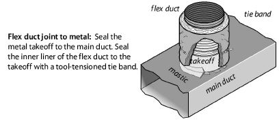
✓ Stretch flex duct and support it every 4 feet with a 1.5-inch duct support.
✓ Use tool-tensioned plastic tie bands to join both the inner liner and the outer liner of the flex duct to the rigid duct or a fitting on the fan or termination fitting.
✓ Install a screw to secure the flex duct and tie band to the metal duct between the tie band and the end of the metal duct.
✓ Flexible air duct material must meet UL 181, NFPA 90A/90B, International Mechanical Code, or the Uniform Mechanical Code.
10.4 Commissioning Ventilation Systems
Commission new, retrofitted and serviced whole-dwelling ventilation systems to verify that the systems function according to design and the ASHRAE 62.2 standard.
✓ Verify that all the required ventilation-system components are present and connected correctly.
✓ Use airflow and pressure manometers that are appropriate for the operating range and that render accuracy of ± 10%.
✓ Measure total airflow, room airflows, and total static pressure to verify that these measurements are within design specifications.
✓ Adjust fan speed, dampers, and registers as necessary to bring airflow into conformance with design specifications.
✓ Verify that all sensors and controls function correctly. Check intermittent or continuous operation, verify sensor operation, record control settings, and observe the sequence of operation.
10.5 Whole-Dwelling Ventilation Systems
This section discusses three options for design of whole-building ventilation systems.
✓ Exhaust ventilation
✓ Supply ventilation
✓ Balanced ventilation
See “Fan and Duct Specifications” on page 423.
We begin by discussing ducts for all types of ventilation systems.
Exhaust ventilation systems employ an exhaust fan to remove indoor air, which infiltrating outdoor air then replaces.
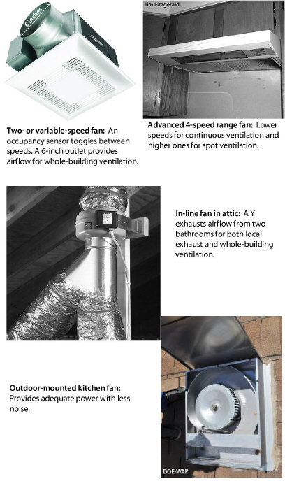
Installing a two-speed bathroom fan is a common ventilation strategy. The new fan runs continuously on low speed for whole-building ventilation. A built-in occupancy sensor switches the fan automatically to a high speed to remove moisture and odors from the bathroom quickly.
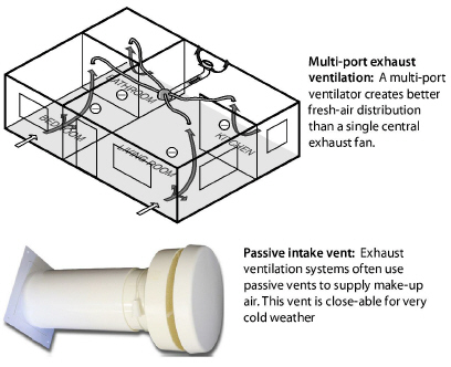
A remote fan that exhausts air from several rooms through ducts (4-to-6 inch diameter) may provide better ventilation for larger more complex dwellings, compared to a single-point exhaust fan.
Exhaust ventilation systems create a negative house pressure, drawing outdoor air in through leaks in the shell. This keeps moist indoor air from traveling through building cavities, which would occur with a positive building pressure. The negative building pressure reduces the likelihood of moisture accumulation in building cavities during the winter months in cold climates.
In hot and humid climates, however, this depressurization can draw moist outdoor air into the home through building cavities. Therefore we recommend supply ventilation for warm humid climates rather than exhaust ventilation.
Single-Family Exhaust-Ventilation-System Specifications
✓ Fans must conform to “Fan Specifications” on page 424.
✓ Ducts must conform to “Duct Materials and Installation” on page 431.
✓ Termination fittings must conform to“Intake and Exhaust Fittings” on page 429.
✓ Use passive intake vents only if you can air seal the building to 1 ACH50 or less. Otherwise the ventilation fans may draw their makeup air from air leaks rather than the passive vents.
Multi-room Exhaust-Ventilation-System Specifications
✓ Evaluate the seal between the roof-mounted ventilator and the its ducts and the roof.
✓ Evaluate ventilation-duct chases for air leakage.
✓ Install backdraft dampers on intermittently operating systems.
✓ Measure airflow through registers to ensure a correct airflow rate. Adjust register size if necessary to decrease or increase ventilation airflow.
✓ Adjust ventilator airflow if building ventilation airflow is either excessive or insufficient.
✓ Insulate ducts outside the thermal boundary to R-8.
✓ Fire dampers must be accessible for inspection and testing.
✓ Educate occupants or building manager on maintenance procedures.
|
SWS Detail: 6.0301 Supply Ventilation; 6.0301.1 Fresh Air Intake In Forced Air System; 6.0301.2 Dedicated Air Handler for Multiple Dwellings |
Supply ventilation, using the home’s air handler, is never operated continuously as with exhaust ventilation because the furnace or heat-pump blower is too large and would over-ventilate the home and waste electrical energy. Supply ventilation may not be appropriate for tight dwellings in very cold climates because supply ventilation can push moist indoor air through exterior walls, where moisture can condense on cold surfaces.
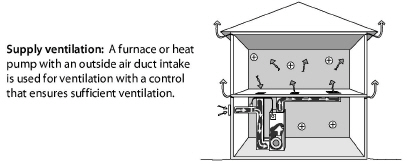
Motorized Outdoor-Air Damper
A motorized damper that opens when the air-handler blower operates must control outdoor-air supply. The furnace/air conditioner heats or cools the outdoor air as necessary before delivering it to the living spaces.
The damper control estimates how much ventilation air is needed. The damper closes after the required amount of ventilation air has entered during heating or cooling. The control also activates the damper and the blower for additional ventilation air as needed without heating or cooling the air during mild weather.
Supply-Ventilation System Requirements
Supply ventilation and sometimes balanced ventilation typically use the furnace or heat pump to move ventilating air. Comply with these specifications.
✓ The existing duct system must leak less than 10% of the air handler flow when measured at 25 Pa. WRT outside.
✓ Install intake to pull air from the outdoors, not including unconditioned spaces such as attics, crawl spaces, and garages.
✓ Install intake above local snow or flood line and a minimum of 10 feet from contaminant sources or exhaust outlets.
✓ Install intake a minimum of 18 inches above an asphalt based roof.
✓ Install intake a minimum of 6 inches from grade.
✓ The outdoor air must flow through a MERV 8 or better air filter before flowing through heating and cooling equipment.
✓ Ducts must conform to “Duct Materials and Installation” on page 431.
✓ Termination fittings must comply with“Intake and Exhaust Fittings” on page 429.
✓ See also "Fan Installation" on page 425.
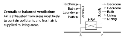
Balanced ventilation systems exhaust stale air and provide fresh air through a ducted distribution system. Of the three ventilation systems discussed here, balanced systems do the best job of controlling pollutants in a building. However weatherization contractors seldom install them because of their high cost and high-maintenance demands.
Balanced systems move equal amounts of air into and out of the home. Most balanced systems incorporate heat-recovery ventilators or energy-recovery ventilators that reclaim heat and moisture from the exhaust air stream.
Balanced ventilation systems can improve the air quality and comfort of a building, but they require a high standard of care. Testing and commissioning are vital during both the initial installation and periodic service calls.
See also "Supply-Ventilation System Requirements" on page 437.
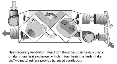
Heat-Recovery and Energy-Recovery Ventilators
The difference between heat-recovery ventilators (HRVs) and energy-recovery ventilators (ERVs) is that HRVs transfer heat only, while ERVs transfer both sensible heat and latent heat (moisture) between air streams.
HRVs are often installed as balanced whole-building ventilation systems. The HRV core is an air-to-air heat exchanger in which the supply and exhaust air streams pass one another and exchange heat without mixing.
The dwelling’s residents can maintain good indoor air quality by using spot ventilation together with opening windows and doors. Depending on climate and season, residents can control natural ventilation to provide clean air, comfort, and energy efficiency.
✓ Choose windows and screen doors in strategic locations to ventilate using prevailing winds.
✓ Make sure that windows and screen doors, chosen for ventilation, open and close and have effective insect screens.
✓ Open windows to provide make-up air when an exhaust fan or the clothes dryer is operating.
✓ Understand that dust and pollen may enter through windows or screen doors and consider the consequences.
10.5.5 Rooftop-Unit (RTUs) Economizer Ventilation
|
SWS Detail: 6.0301.1 Fresh Air Intake In Forced Air System; 6.0301.2 Dedicated Air Handler for Multiple Dwellings |
Many buildings, particularly those with RTUs use economizers as their ventilation system. The delivered ventilation air is part outdoor air and part indoor air. The outdoor air dilutes pollutants and the indoor air provides mixing and moderation. Economizers don’t normally have heat recovery or energy recovery function, so economizer ventilation has an energy penalty compared to a heat recovery ventilators.
Mild climates are ideal for ventilating with an economizer. When buildings use an economizer for ventilation, its dampers are open a small amount while the HVAC system is heating, cooling, or operating on the fan-only option. The fan-only control setting functions when you need ventilation, but not heating or cooling.
To run efficiently, the economizer requires a programmable thermostat that tracks the amount of ventilation air delivered during the free cooling mode and during the ventilation mode.
See also "Supply-Ventilation System Requirements" on page 437.
10.6 Garage Exhaust Ventilation
Attached garages, particularly garages beneath living areas, may require exhaust ventilation to prevent indoor CO contamination. Only consider garage exhaust ventilation when all attempts to air-seal the garage from the house were insufficient.
✓ Use pressure diagnostics to assist in determining the level of connection from the garage to the house and in making the determination for the need to add garage ventilation.
✓ For single family homes, install 100-CFM-capacity exhaust fans with an efficacy of 3.8 cfm/watt or more on the exterior wall or surface mounted inside the garage.
✓ Make sure the fan doesn’t cause an unacceptable depressurization in a nearby CAZ. Provide pressure-relief if necessary.
✓ If the fan doesn’t contain an integrated damper, install a damper that opens in the direction of the desired flow and closes when the system is off
✓ For larger multifamily garages, do thorough air sealing and then provide exhaust ventilation necessary to reduce indoor CO to a negligible level.
✓ Operate the fan using an occupancy sensor with a 15-minute runtime or continuous for larger garages as necessary.
See also "Garages Underneath Living Areas" on page 221.
|
SWS Detail: 6.0301.1 Fresh Air Intake In Forced Air System; 6.0301.2 Dedicated Air Handler for Multiple Dwellings; 6.0304.1 Multi-Story Passive System |
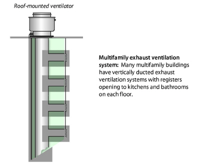
Exhaust-only ventilation is the most common ventilation strategy for multifamily buildings. Vertical chases surround the ventilation ducts and installers cut holes in the chase for the ventilation registers/grills.
Forced-air HVAC systems also provide ventilation to multifamily buildings. The HVAC system delivers a portion of heated and cooled air as outdoor ventilation air.
See the following sections for more information on multifamily ventilation.
• “General Fan and Ventilator Specifications” on page 424
• “Fan Installation” on page 425
• “Whole-Dwelling Ventilation Systems” on page 433
• “Air Filtration for Indoor Air Quality” on page 443
• “Rooftop-Unit (RTUs) Economizer Ventilation” on page 440
10.8 Air Filtration for Indoor Air Quality
Ventilation isn’t effective at removing small particles. Efficient air filters can reduce particle pollution in homes where particles are a air-quality problem. Suggest that customers run their air handlers during heavy air pollution in cities, proximity to dirt roads, seasonal forest fires, and other particle-generating events.
You can run an air-handler fan using the “fan only” setting on a thermostat. You can even program the fan to run for a period each day using a programmable thermostat.
The best places for filters are in forced-air HVAC systems or in balanced ventilation systems. Room air cleaners can also be effective particle removers if there is natural circulation among rooms.
Air filters affect the airflow and energy consumption of forced air HVAC systems and balanced ventilation systems. Before choosing the type of air filter and deciding to use the filter to remove particles, consider the filter’s MERV rating and a building’s need for particle removal.
10.8.1 Installing Filters for Outdoor Air
|
SWS Detail: 6.0303.1 HRV/ERV Installation; 6.0301.2 Dedicated Air Handler for Multiple Dwellings; 6.0301.1 Fresh Air Intake In Forced Air System |
Provide filters for outdoor air supplied through ducted ventilation systems and observe these specifications.
✓ All fan-supplied outdoor air must pass through a filter before combining with conditioned air.
✓ Select a filter with a MERV rating of 8 or greater.
✓ The filter’s pressure drop must not result in insufficient HVAC airflow.
✓ Install the filter on the inlet side of the fan.
✓ Make the filter accessible for changing or cleaning.
✓ Instruct the occupants or building manager on how and when to service the filter.
|
SWS Detail: 4.0188.2 Unconditioned Attic Ventilation; 4.0102.2 SPF Roof Insulation - Vented Roof Deck |
Attic ventilation has the following functions.
• To keep the attic insulation and the attic’s other building materials dry by circulating dry outdoor air through the attic.
• To prevent ice dams in cold weather by preventing snow melt and keeping the roof deck cold during the winter.
• To remove solar heat from the attic during the summer.
10.9.1 Attic Ventilation as a Solution for Moisture Problems
The best way to keep attic insulation dry is to air-seal the attic floor to block moist indoor air from entering the attic. Adding attic vents may help to solve certain attic moisture problems.
• Seasonal moisture deposition.
• Ice damming in areas that currently lack high and low vents.
Adding attic vents won’t solve these attic moisture problems.
• Moisture deposited by air leaks between the living space and the attic.
• Rain driven through attic vents.
• Roof leaks that dampen building materials beyond the capacity of the vents to dry.
10.9.2 When to Install Attic Ventilation
Install more attic ventilation only if you believe that the home needs one of the attic-ventilation functions listed above. Consider the following discussion points.
• Don’t increase attic ventilation without first sealing attic air leaks and testing the attic air barrier for adequate airtightness.
• Avoid cutting new vents through the roof to avoid the possibility of roof leaks.
• Attic ventilation may not provide a useful function in some climates, such as persistently damp climates or windy, rainy climates.
Important note: The IRC offers an outright exception to ventilating attics if a code official determines that “atmospheric or climatic conditions” aren’t favorable to attic ventilation.
10.9.3 Attic Ventilation Requirements
|
SWS Detail: 4.0188.2 Unconditioned Attic Ventilation; 4.0102.2 SPF Roof Insulation - Vented Roof Deck |
Always vent exhaust fans directly to outdoors (through a soffit, gable, or wall) and never into a ventilated attic.
Net free area is the area of the vent minus the vent’s solid obstructions such as screens and louvers. The net free area is typically 50% to 70% of the gross vent area.
The IRC and SWS state these requirements for attic ventilation.
✓ Provide a maximum ratio of one square foot of net free vent area to 150 square feet of attic area.
✓ The IRC requires only one square foot of net free area per 300 square feet of attic area for cool-climate ceilings, that have an interior vapor barrier, or well distributed ventilation (high and low), or with thorough air-sealing of the ceiling.
✓ Vents must have screens, with 1/4-to-1/16 inch or less opening, to prevent the entry of pests and to reduce the entry of snow and rain.
✓ Vertical vents must have louvers to deflect rain.
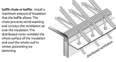
✓ Install vent chutes or baffles to prevent blown insulation and spray-foam insulation from entering the space between soffit vents and the attic.
✓ The baffles should allow the maximum amount of insulation to be installed over top plates without restricting ventilation paths. Vent chutes or baffles also help prevent the wind-washing of insulation caused by cold or hot air entering soffit vents. They should extend upwardly along the rafter to at least 4 inches above the finished insulation level.
✓ For spray-foam insulation installed under the roof deck, vent chutes or baffles can create a duct that carries ventilating air along the underside of the roof deck, which keeps the roof deck dry and cold in winter. See “Unvented Spray Foam Roof-Deck Insulation” on page 171.
✓ Don’t install power ventilators to increase attic ventilation because of their energy consumption and doubtful effectiveness.
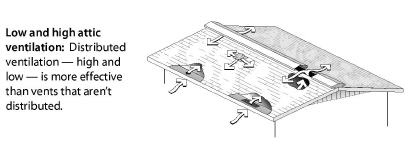
High and Low Vents
A combination of high and low vents is the best way to move ventilating air through the attic. Soffit vents and ridge vents are an ideal combination for high-low attic ventilation. However, gable vents and roof vents, located high or low, also create acceptable ventilation.
Power ventilators have limited value ventilating attics for air-conditioning energy savings or moisture mitigation.
• Power ventilators typically run longer than necessary.
• Power ventilators often consume more electricity than they save in reduced air conditioning.
• Power ventilators can pull conditioned air out through ceiling air leaks, counteracting their ventilating or cooling benefit.
According to the IRC, new attics may be unventilated if the two conditions listed here are both met.
1. There is no vapor barrier installed in the ceiling.
2. The roof assembly is insulated with an air-impermeable insulation, such as high-density sprayed polyurethane, to the bottom of the roof sheathing or foam board on the top side of the roof sheathing.
Before taking steps to improve crawl-space ventilation, comply with these requirements.
✓ The crawl space should have an access hatch or door that is adequate for a worker or resident to enter or exit.
✓ Correct grading, drainage, and gutter-and-downspout problems related to crawl-space moisture problems as specified in “Ground-Water Drainage” on page 37.
✓ Install a ground moisture barrier as specified in “Ground-Moisture Barriers” on page 42.
✓ Install a sump pump with its discharge drained to daylight or a French drain to drain persistent standing water.
10.10.1 Naturally Ventilated Crawl Spaces
When insulating the floor, the crawl space is usually ventilated naturally through passive vent openings in the foundation wall. A ground moisture barrier protects the floor insulation and other building materials from moisture. The vent openings can remove small amounts of moisture from the crawl space. Two specifications apply to ventilated crawl spaces.
1. A crawl-space with a ground-moisture barrier may have vent openings equal to 1 square foot of vent area to 300 square feet of crawl-space floor area. A minimum of two vents should be installed on opposite corners of the crawl space.
2. In a dry crawl space with a ground-moisture barrier, ventilation openings may be minimized to one square foot of net free ventilation area for every 1500 square feet of crawl-space floor area, according to the 2012 IRC.
10.10.2 Power-Ventilated Crawl Spaces
The IRC allows you to seal the crawl-space vents completely when you insulate the foundation walls and power-ventilate the crawl space. These three specifications apply to power-ventilated or conditioned crawl spaces.
1. Remove moisture sources like standing water and install a seam-sealed and edge-sealed ground-moisture barrier, before sealing the foundation vents.
2. The IRC requires 1 CFM per 50 square feet of crawl space floor area in continuous powered exhaust ventilation. The IRC requires openings from the crawl space into the home so that make-up air comes from the living space. Some installers depend on floor air leakage to provide make-up air instead of intentional openings between the home and crawl space.
3. An acceptable alternative to option 2 is controlling the exhaust fan with a dehumidistat (moisture sensitive control). Such an exhaust fan typically operates continuously until the crawl space is dry and then intermittently after that. This option isn’t IRC-approved.
10.10.3 Conditioned Crawl Spaces
The IRC requires 1 CFM per 50 square feet of crawl space floor area in conditioned supply air from a forced-air system. The IRC requires openings from the crawl space into the home for this option. The conditioned option requires code-compliant level of foundation insulation appropriate for the home’s climate.
The conditioned crawl space, although allowed by the IRC, may be an ineffective moisture-and-energy solution for existing crawl spaces, especially in dry locations. In humid climates with damp crawl spaces, the conditioned crawl space has succeeded in reducing moisture problems and even energy costs, when combined with an airtight ground moisture barrier and foundation insulation.
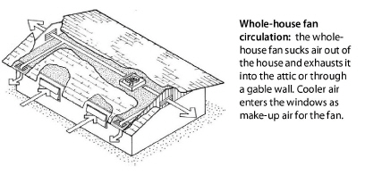
Ventilation cooled dwellings for centuries before the invention of air conditioning. Ventilation is still an effective method for clients who can’t afford air conditioning. Ventilate with fans during the coolest parts of the day and night, and close the windows during the hottest periods.
Whole-house fans range in diameter from 24 inches to 42 inches, with capacities ranging from 3,000 to 10,000 cubic feet per minute (cfm). The capacity of the fan in cfm is rated for two different conditions: 1) free air; and 2) air constricted by 1 inch of static pressure. The second condition is closer to the actual operating conditions of the fan in a home, and the cfm rating at 1 inch of static pressure may still be 10 to 30 percent higher than the actual volume of air moved by the installed whole-house fan. This means you should probably install a fan with a greater capacity than the sizing recommendations that follow.
Whole-house fans require 2 to 4 times the normal area of attic vent openings. Install a minimum of 1 square foot of net free area for every 750 cfm of fan capacity. However, more vent area is better for optimal whole-house-fan performance because the extra vent area increases airflow.
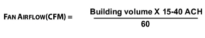
To estimate the suitable size of a whole-house fan in cubic feet per minute,
1. First determine the volume of the building in cubic feet. Multiply the square footage of the floor area in your building that you want to cool by the height from floor to ceiling.
2. Take that volume and multiply by 15 to 40 air changes per hour, depending on how much ventilation you want.
3. Then, divide by 60 minutes to get cubic feet per minute of capacity for the whole-house fan.
Seasonal Cover
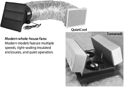
Some fans come with a tight-sealing winter cover. If the fan doesn’t have such a cover, or if the attic access doesn’t allow you to cover the fan easily, then you can fabricate a cover for the grill on the ceiling. A seasonal cover, held in place with rotating clips or spring clips and sealed with foam tape, works well.
If the clients switch between air conditioning and cooling with a whole-house fan as the summer weather changes, build a tightly-sealed, hinged door for the fan opening that is easy to open and close when they switch cooling methods.
Comply with these specifications to install an operable cover.
✓ Install an operable cover for the fan enclosure that opens when the fan operates and closes when the fan turns off.
✓ Operable cover must seal airtight when closed.
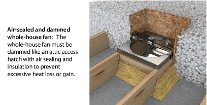
Insulation Dam
✓ Insulate fan enclosure to a minimum of R-20.
✓ Install insulation in full contact with the enclosure.
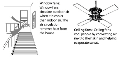
Window fans are best used in windows facing the prevailing wind or away from it to provide cross ventilation. Window fans can augment any breeze or create a breeze when the air is still. If the wind direction changes in your area, use reversible type window fans so you can either pull air into the home or push air out, depending on which way the wind is blowing. Experiment with positioning the fans in different windows to see which arrangement works best.
Air circulating fans are very effective cooling energy savers. Air circulating fans may allow a 4 degree rise in the thermostat setting with no decrease in comfort.
Use circulating fans with air conditioners, evaporative coolers, whole-house fans, or by themselves. Circulating fans save cooling energy by increasing air movement over the skin to help occupants feel cooler.
Ceiling Fans
Ceiling fans and various types of portable fans provide more comfort at less cost than any other electrically powered cooling strategy. Options include: small personal fans that sit on tabletops, or heavier units that sit on the floor or on metal stands with wheels.
Ceiling fans produce high air speeds with less noise than oscillating fans or box fans. High quality ceiling fans are generally more effective and quieter than cheaper ones. Ceiling fans are a key element to providing low-cost comfort to a home.
Comply with these specifications when selecting and installing a ceiling fan.
✓ Fan and lighting must be ENERGY STAR® qualified, equivalent, or better.
✓ Fan must be compatible with the existing switching and wiring configuration.
✓ Fan must be of similar functionality and size as the one you’re replacing and carry a minimum of a 1-year warranty.
✓ Provide occupants/owners with user's manual, warranty information, installation instructions, and installer contact information.
|
SWS Detail: 5.0109.5 Evaporative Coolers; 5.0108.5 Evaporative Coolers |
Evaporative coolers (also called swamp coolers) are an effective energy efficient cooling strategy in dry climates. An evaporative cooler is a blower and wetted pads installed in a compact louvered air handler.
Evaporative coolers employ different principles from air conditioners because they reduce air temperature without removing heat from the air. They work well only in climates where the summertime relative humidity remains less than 50%. They compare to an air conditioner with a SEER between 30 and 40, which is 2 to 3 times the SEER of the most efficient air conditioners.
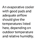
Installers mount evaporative coolers on a roof, through a window or wall, or on the ground. The cooler can discharge air directly into a room or hall or it can be connected to ducts for distribution to numerous rooms.
.jpg)
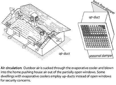
The evaporative cooler’s blower moves outdoor air through water-saturated pads, reducing the air’s temperature to below the indoor air temperature. The blower moves this evaporatively cooled outdoor air into the house, pushing warmer indoor air out through open windows or dedicated up-ducts.
A water pump in the reservoir circulates water through tubes into a drip trough, which then drips water into the thick pads. A float valve connected to the home’s water supply keeps the reservoir supplied with fresh water to replace the water that evaporates.
Opening windows in occupied rooms, and closing windows in unoccupied rooms concentrates the cooling effect where residents need it. Experiment to find the right windows to open and how wide to open them. If the windows are open too wide hot air will enter. If the windows are not open far enough humidity will rise, and the air will feel sticky.
Up-Ducts
Up-ducts are one-way vents from the living space to the attic. Up-ducts are for occupants who want to avoid opening windows for security reasons. The cool air from the evaporative cooler flows into the living space, through the up-ducts, into the attic, and out the attic vents. Up-ducts can be a significant source of air leakage. They may be temporarily sealed seasonally or even removed during weatherization.
Evaporative Cooler Sizing and Selection
Evaporative coolers are rated in cubic feet per minute (cfm) of airflow they deliver. Airflow capacity ranges from 2000 to 7000 cfm. Recommendations vary from 2-to-3 cfm per square foot of floor space for warm dry climates and 3-to-4 cfm/sf for hot desert climates.
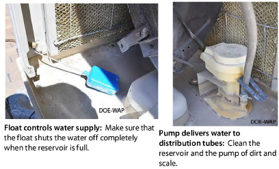
Evaporative Cooler Maintenance
Evaporative coolers see a lot of water, air, and dirt during operation. Dirt is the enemy of evaporative-cooler operation. Evaporative coolers process a lot of dirt because their aspen pads are good filters for dusty outdoor air.
Airborne dirt that sticks to the cooler pads washes into the reservoir. Most evaporative coolers have a bleed tube or a separate pump that changes the reservoir water during cooler operation to drain away dirty water. Evaporative coolers needs regular cleaning, depending on how long the cooler runs and how well the dirt-draining system is working. Be sure to disconnect the electricity to the unit before servicing or cleaning it.
Observe these general specifications for maintaining evaporative coolers.
✓ Aspen pads can be soaked in soapy water to remove dirt. Clean louvers in the cooler cabinet when you clean or change pads. Replace the pads when they become un-absorbent, thin, or loaded with scale and entrained dirt.
✓ If there is a bleed tube, check discharge rate by collecting water in a cup or beverage can. You should collect a cup in three minutes or a can in five minutes.
✓ If the cooler has two pumps, one is a sump pump. The sump pump drains the sump every five to ten minutes of cooler operation.
✓ If there is noticeable dirt on the blower’s blades, clean the blower.
✓ Clean the holes in the drip trough that distributes the water to the pads.
✓ Clean the reservoir every year to remove dirt, scale, and biological matter.
✓ Pay particular attention to the intake area of the circulating pump during cleaning. Debris can get caught in the pump impeller and stop the pump.
✓ Check the float assembly for positive shutoff of water when the sump reaches its level. Repair leaks and replace a leaky float valve.
✓ Investigate signs of water leakage and repair water leaks.

|
Outdoor Relative Humidity % |
||||||||||||||||
|---|---|---|---|---|---|---|---|---|---|---|---|---|---|---|---|---|
|
|
|
2 |
5 |
10 |
15 |
20 |
25 |
30 |
35 |
40 |
45 |
50 |
55 |
60 |
65 |
70 |
|
Outdoor Temperature F˚ |
75 |
54 |
55 |
57 |
58 |
59 |
61 |
62 |
63 |
64 |
65 |
66 |
67 |
68 |
69 |
70 |
|
80 |
57 |
58 |
60 |
62 |
63 |
64 |
66 |
67 |
68 |
71 |
72 |
73 |
74 |
76 |
76 |
|
|
85 |
61 |
62 |
63 |
65 |
67 |
68 |
70 |
71 |
72 |
73 |
74 |
75 |
76 |
77 |
79 |
|
|
90 |
64 |
64 |
67 |
69 |
70 |
72 |
74 |
76 |
77 |
78 |
79 |
81 |
82 |
83 |
84 |
|
|
95 |
67 |
68 |
70 |
72 |
74 |
76 |
78 |
79 |
81 |
82 |
84 |
85 |
87 |
|
||
|
100 |
69 |
71 |
73 |
76 |
78 |
80 |
82 |
83 |
85 |
87 |
88 |
|
||||
|
105 |
72 |
74 |
77 |
79 |
81 |
84 |
86 |
88 |
89 |
|
||||||
|
110 |
75 |
77 |
80 |
83 |
85 |
87 |
90 |
92 |
|
|||||||
|
115 |
78 |
80 |
83 |
86 |
89 |
91 |
94 |
|
||||||||
|
120 |
81 |
83 |
86 |
90 |
93 |
95 |
|
|||||||||
|
125 |
83 |
86 |
90 |
93 |
96 |
|
||||||||||