|
SWS Detail: 5.3003.4 Evaluating Electrical Service, 5.3003.11 Heating and Cooling Controls, 5.3003.26 Electrical Service—Mid and High Rise |
The forced-air system consists of an air handler (furnace, heat pump, air conditioner) with its heat exchanger along with attached ducts. The annual system efficiency of forced-air heating and air-conditioning systems depends on the following issues.
• Duct leakage
• System airflow
• Blower operation
• Balance between supply and return air
• Duct insulation levels
The evaluation and improvement of ducts has a logical sequence of steps.
1. Solve the airflow problems because a contractor might have to replace ducts or install additional ducts.
2. Determine whether the ducts are located inside the thermal boundary or outside it.
3. Evaluate the ducts’ air leakage and decide whether duct-sealing is important and if so, find and seal the duct leaks.
4. If supply ducts are outside the thermal boundary or if condensation is an air-conditioning problem, insulate the ducts.
8.13.2 Solving Airflow Problems
You don’t need test instruments to discover dirty blowers or disconnected branch ducts. Find these problems before measuring duct airflow, troubleshooting the ducts, or sealing the ducts. These steps precede airflow measurements.
1. Ask the customer about comfort problems and temperature differences in different rooms of the home.
2. Based on the customers comments, look for disconnected ducts, restricted ducts, and other obvious problems.
3. Inspect the filter(s), blower, and indoor coil for dirt. Clean them if necessary. If the indoor coil isn’t easily visible, a dirty blower means that the coil is probably also dirty.
4. Look for dirty or damaged supply and return grilles that restrict airflow. Clean and repair them.
5. Look for closed registers or closed balancing dampers that could be restricting airflow to uncomfortable rooms.
6. Notice kinked, or un-stretched flex duct and repair the flex duct as necessary.
7. Notice moisture problems like mold and mildew. Moisture sources, like a wet crawl space, can overpower air conditioners by introducing more moisture into the air than the air conditioner can remove.
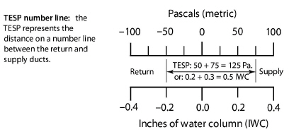
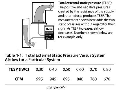
Measuring Total External Static Pressure (TESP)
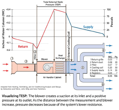
The blower creates the duct pressure that you can measure in inches of water column (IWC) or pascals. The return static pressure is negative and the supply static pressure is positive. Total external static pressure (TESP) is the sum of the absolute values of the supply and return static pressures. Absolute value means that you ignore the positive or negative signs when adding supply static pressure and return static pressure to get TESP. This addition represents the distance on a number line as shown in the illustration here.
TESP gives a rough indicator of whether airflow is adequate or not. The greater the TESP, the less the airflow. The supply and return static pressures by themselves can indicate whether the supply or the return or both sides are restricted. For example, if the supply static pressure is 0.10 IWC (25 pascals) and the return static pressure is –0.5 IWC (-125 pascals), you can assume that most of the airflow problems are due to a restricted or undersized return.
The TESP gives a rough estimate of airflow if the manufacturer’s graph or table for static pressure versus airflow is available.
1. Attach two static pressure probes to tubes leading to the two ports of the manometer. Attach the high-side port to the probe inserted downstream of the air handler in the supply duct. The other tube goes upstream of the air handler in the return duct. The manometer adds the supply and return static pressures to measure TESP.
2. Consult manufacturer’s literature for a table of TESP versus airflow for the blower or the air handler. Find airflow for the TESP measured in Step 1.
3. Measure pressure on each side of the air handler to obtain both supply and return static pressures separately. This test helps to locate the main problems as related to either the supply or the return.
Static Pressure Guidelines
Air handlers deliver their airflow at TESPs ranging from 0.30 IWC (75 Pascals) to 1.0 IWC (250 Pascals) as found in the small buildings. Manufacturers maximum recommended static pressure is usually 0.50 IWC (125 pascals) for standard air handlers. TESPs greater than 0.50 IWC indicate inadequate airflow in standard residential forced-air systems.
The popularity of pleated filters, electrostatic filters, and high-static high-efficiency evaporator coils, prompted manufacturers to introduce premium air handlers that can deliver adequate airflow at a TESP of greater than 0.50 IWC (125 pascals).
Premium residential air handlers can provide adequate airflow with TESPs of up to 0.90 IWC (225 pascals) because of their more powerful blowers and variable-speed blowers. TESPs greater than 0.90 IWC indicate the possibility of inadequate airflow in these premium residential air handlers.
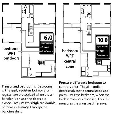
8.13.3 Unbalanced Supply-Return Airflow Test
Closing interior doors often separates supply registers from return registers in homes with central returns. A bedroom without a return register and with a closed door restricts the bedroom air from returning to the air handler. This restriction pressurizes bedrooms and depressurizes the central areas near return registers. These pressures can drive air leakage through the building shell, create moisture problems, and bring pollutants in from the crawl space, garage, or CAZ.
The following tests use only the air handler and a digital manometer to evaluate whether the supply air can flow back to the return registers relatively unobstructed. Activate the air handler and close interior doors.
1. Measure the pressure difference between the home’s central living area and the outdoors with a digital manometer.
2. Measure the bedrooms’ pressure difference with reference to outdoors.
3. Or, you can measure the pressure difference between the central zone and the bedroom.
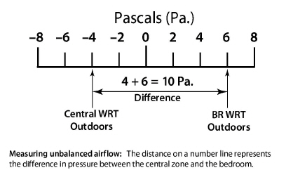
If the difference between the bedroom and central zone is more than 3.0 pascals with the air handler operating, pressure relief is desirable. Like TESP, disregard the positive or negative signs, and add the absolute values.
To estimate the amount of pressure relief needed, slowly open the bedroom door until the pressure difference drops below 1 pascal.
Estimate the surface area of that door opening. This is the area of the permanent opening required to provide pressure relief. Pressure relief may include undercutting the door, installing transfer grilles or installing jumper ducts.
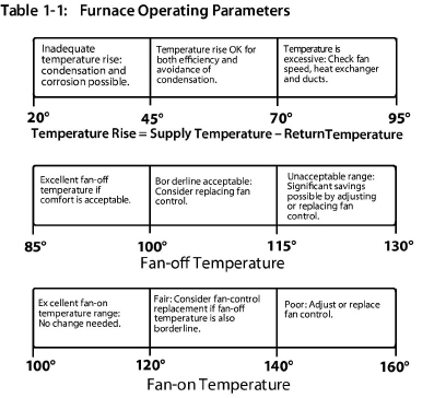
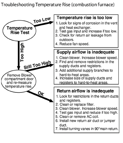
8.13.4 Evaluating Furnace Performance
|
SWS Detail: 5.3003.4 Evaluating Electrical Service, 5.3003.26 Electrical Service—Mid and High Rise |
The effectiveness of a furnace depends on its temperature rise, fan-control temperatures, and flue-gas temperature. For efficiency, you want a low temperature rise. However, the furnace must maintain a minimum flue-gas temperature to prevent corrosion in the venting of 70+ and 80+ AFUE units.
Apply the following furnace-operation standards to maximize the heating system’s seasonal efficiency and safety.
✓ Perform a combustion analysis as described in “Gas Burner Safety & Efficiency Service” on page 291.
✓ Check temperature rise after 5 minutes of operation. Refer to manufacturer’s nameplate for acceptable temperature rise (supply temperature minus return temperature). The temperature rise should be between the minimum and maximum temperature rise on the nameplate (usually 40°F and 70°F). Prefer the lower end of this range for energy efficiency.
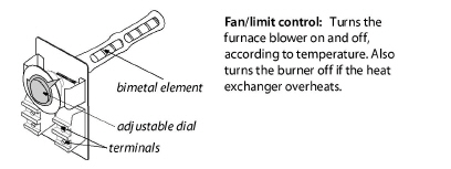
✓ With temperature-activated controls, verify that the fan-on temperature is 120–140° F. The lower the better.
✓ With time-activated fan controls, verify that the fan is switched on with the shortest time delay available if it’s adjustable. The control should switch the fan off when the fan off temperature is 20° to 30° above the measured return-air temperature.
✓ Verify that the high-limit controller shuts the burner off before the furnace temperature reaches 200°F.
✓ Verify that there is a strong noticeable airflow from all supply registers.
✓ Adjust fan control to conform to the operating parameters on the diagram or replace the fan control if this adjustment fails. Some fan controls aren’t adjustable.
✓ Adjust the high limit control to conform to the operating parameters on the diagram, or replace the high-limit control.
✓ All forced-air heating systems must deliver supply air and collect return air only from inside the conditioned rooms of the house. Taking return air from an un-heated area of the house such as an unconditioned basement or a crawl space isn’t acceptable.
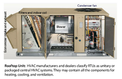
8.13.5 Rooftop Units (Air Handlers)
|
SWS Detail: 5.3003.4 Evaluating Electrical Service, 5.3003.26 Electrical Service—Mid and High Rise, 5.3003.11 Heating and Cooling Controls |
Rooftop units (RTUs) are air handlers located on roofs or on slabs or platforms outdoors. RTUs may contain one or more of the following.
• A combustion furnace
• All the components of an air conditioner (packaged or unitary air conditioner)
• All the components of an heat pump (packaged or unitary heat pump)
• Outdoor-air damper with another damper, called an economizer for ventilation and free cooling.
A controller in the economizer measures the temperature (and humidity in humid climates) of the outdoor air. When the outdoor conditions are favorable, the control switches the air conditioning compressor off and cools the building with outdoor air instead. The economizer uses far less cooling energy compared to air conditioning.
Economizers typically operate at night when the outdoor air is cooler than the indoor air in a process known as “free cooling”. Economizers mix enough outdoor air into the indoor air in order to meet the thermostat setpoint (which may be lower than the AC setpoint), without using the compressor.
Fresh air that economizers exchange with indoor air while they save cooling energy at night can also count as ventilation. Therefore the ventilation system can run for fewer hours and avoid operating during the day’s peak electrical load.
RTU Maintenance and Improvement
Because RTUs are located outdoors, they are even more likely to be neglected compared to indoor air handlers. Fortunately though, the RTU’s components are more accessible compared to indoor air handlers.
Consider the following maintenance and improvements for RTUs.
✓ Clean or change filters, provide extra filters, and educate the building owner on filter maintenance.
✓ Test the combustion furnace as you would an indoor furnace.See “Combustion-Safety Evaluation” on page 253.
✓ Clean the evaporator and condenser coils as specified on page 379.
✓ Test the RTU and its ducts for air leakage because many RTUs systems have high duct leakage. See “Air Filter Effectiveness” on page 339.
✓ Test and adjust the economizer to maximize its benefit for both free cooling and ventilation. This requires an elite HVAC controls technician.
✓ Educate the building owner or operator on economizer function and control. Replace the thermostat, if necessary to accommodate optimal economizer functioning. Note: Economizers functioning isn’t intuitive and therefore many, if not most, economizers function poorly.
8.13.6 Recommended Airflow for Air Handlers
The air handler’s recommended airflow depends on its heating or cooling capacity. For combustion furnaces, provide 11-to-15 CFM of airflow for each 1000 BTUH of output. Verify at least 2 square inches of cross-sectional area for each 1000 BTUH of furnace input in both the supply plenum and the return plenum in order to achieve this airflow.
Central air conditioners and heat pumps should deliver 400 CFM ±20% of airflow per ton of cooling capacity (one ton equals 12,000 BTUH). This airflow standard typically requires a duct system with at least 6 square inches of cross-sectional area of both supply plenum and return plenum for each 1000 BTUH of air-conditioning or heat-pump capacity.
|
Gas Furnaces |
Heat Pumps & Air Conditioners |
|||
|---|---|---|---|---|
|
BTUH Input |
In2 Area (Supp. & Ret.) |
BTUH Capacity |
In2 Area (Supp. & Ret.) |
Tons (capacity) |
|
40,000 |
80 |
24,000 |
144 |
2 |
|
60,000 |
120 |
30,000 |
180 |
2.5 |
|
80,000 |
160 |
36,000 |
216 |
3 |
|
100,000 |
200 |
42,000 |
252 |
3.5 |
|
120,000 |
240 |
48,000 |
288 |
4 |
|
140,000 |
280 |
54,000 |
324 |
4.5 |
|
160,000 |
320 |
60,000 |
360 |
5 |
|
Each trunk, supply and return, should have the recommended cross-sectional area shown here. Courtesy: Bruce Manclark |
||||
8.13.7 Improving Forced-Air System Airflow
Inadequate airflow is a common cause of comfort complaints. When the air handler is on there should be a strong airflow out of each supply register. Low register airflow may mean that a branch duct is blocked or separated, or that return air from the room to the air handler isn’t sufficient.
When low airflow is a problem, consider specifying the following improvements as appropriate from your inspection.
✓ Clean or change filter. Select a less restrictive filter (lower MERV rating) if you need to reduce static pressure substantially.
✓ Clean air handler’s blower.
✓ Clean the air-conditioning coil or heat pump coil. If the blower is dirty, the coil is probably also dirty.
✓ On a condensing furnace, clean the secondary heat exchanger coil.
✓ Increase blower speed.
✓ Make sure that balancing dampers to rooms that need more airflow are wide open.
✓ Lubricate the blower motor, and check tension on drive belt.
Duct Improvements to Increase Airflow
Consider specifying the following duct changes to increase system airflow and reduce the imbalance between supply airflow and return airflow.
✓ Modify the filter installation to allow easier filter changing, if filter changing is currently difficult.
✓ Remove obstructions to registers and ducts such as rugs, furniture, and objects placed inside ducts (children’s toys and water pans for humidification, for example).
✓ Remove kinks from flex duct, and replace collapsed flex duct and deteriorating fiberglass duct board.
✓ Remove excessive lengths of slacking flex duct, and stretch the duct to enhance airflow.
✓ Perform a Manual D sizing procedure to evaluate whether to replace branch ducts that are too small.
✓ Install additional supply ducts, return ducts, and registers as needed to provide heated air throughout the building, especially in additions to the building.
✓ Undercut bedroom doors, especially in homes without return registers in bedrooms.
✓ Repair or replace bent, damaged, or restricted registers. Install low-resistance registers and grilles.
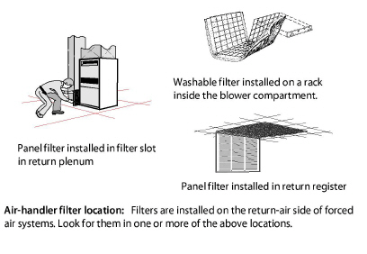
8.13.8 Air Filtration for Air Handlers
Manufacturers equip air handlers with air filters at the factory or recommend that installers install air filters in return ductwork. The purpose of these filters is to protect the blower and heat exchangers from fouling by dust.
Another possible function for air filters is to remove particles from indoor air. This function is useful when the outdoor environment contains a lot of particles, such in large cities, rural areas where wind and agriculture create particulates, or during forest fires.
The most common filter-rating method is the Minimum Efficiency Rating Value (MERV). A higher MERV rating means that the filter removes more particles and a larger fraction of smaller particles.
The MERV rating system divides particles into three size categories: 0.3–1, 1–3, and 3–10 microns. The two smallest categories are the most important for human health, as small respirable particles (PM2.5) can more easily deposit in the lungs compared to larger particles.
The need for high MERV filters depends on the severity of the particle problem in a building. Particles less than 2.5 microns are the most dangerous because they can lodge themselves deep in the lungs. Filtering air with a long-running central air handler or a portable air cleaner can be energy intensive and it may or may not be effective.
The MERV ratings of available HVAC filters range from MERV 3 to MERV 16, with higher ratings removing more particles at smaller sizes. A MERV 3 filter captures large particles — clothing fibers, pollen, and dust mites, but few smaller respirable particles. A MERV16 filter captures more than 95% of all three particle sizes, including bacteria and tobacco smoke. The minimum MERV rating to remove 50% of the respirable 1–3 microns particle-size range is MERV 10. See also "Air Filtration for Indoor Air Quality" on page 418.
Air Filter Pressure and Airflow Effects
Air filters affect the airflow and energy consumption of forced air HVAC systems and balanced ventilation systems. Before choosing the type of air filter, consider its MERV rating and a home’s need for particle removal.
HVAC designers designed air handlers for use with low-MERV filters with a small pressure drop. Changing to higher-MERV filters can cause the filter pressure drop to increase and the system airflow to decrease.
Insufficient airflow may cause blowers to fail prematurely as they struggle to overcome system pressures beyond their design specification. For heating systems, the furnaces may overheat and cycle on their high limit switches. Airflow reductions in cooling systems risk coil icing and premature compressor failure. See also "Air Filtration for Indoor Air Quality" on page 418.
To reduce the resistance of an high-MERV air filter, consider installing steps to accommodate a larger filter with more surface area and less static-pressure drop compared to the existing filter.
• A slanted filter bracket assembly
• An enlarged filter fitting to allow a filter with more surface area
• Filters in each return register instead of only one at the air handler.