9.5 Whole-Dwelling Ventilation Systems
This section discusses three options for design of whole-building ventilation systems.
✓ Exhaust ventilation
✓ Supply ventilation
✓ Balanced ventilation
See “Fan and Duct Specifications” on page 402.
We begin by discussing ducts for all types of ventilation systems.
Exhaust ventilation systems employ an exhaust fan to remove indoor air, which infiltrating outdoor air then replaces.
Installing a two-speed bathroom fan is a common ventilation strategy. The new fan runs continuously on low speed for whole-building ventilation. A built-in occupancy sensor switches the fan automatically to a high speed to remove moisture and odors from the bathroom quickly.
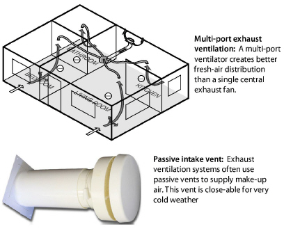
A remote fan that exhausts air from several rooms through ducts (4-to-6 inch diameter) may provide better ventilation for larger more complex dwellings, compared to a single-point exhaust fan.
Exhaust ventilation systems create a negative house pressure, drawing outdoor air in through leaks in the shell. This keeps moist indoor air from traveling through building cavities, which would occur with a positive building pressure. The negative building pressure reduces the likelihood of moisture accumulation in building cavities during the winter months in cold climates.
In hot and humid climates, however, this depressurization can draw moist outdoor air into the home through building cavities. Therefore we recommend supply ventilation for warm humid climates rather than exhaust ventilation.
Single-Family Exhaust-Ventilation-System Specifications
✓ Fans must conform to “Fan Specifications” on page 402.
✓ Ducts must conform to “Duct Materials and Installation” on page 407.
✓ Termination fittings must conform to“Termination Fittings” on page 404.
✓ Use passive intake vents only if you can air seal the building to 1 ACH50 or less. Otherwise the ventilation fans may draw their makeup air from air leaks rather than the passive vents.
Multi-room Exhaust-Ventilation-System Specifications
✓ Evaluate the seal between the roof-mounted ventilator and the its ducts and the roof.
✓ Evaluate ventilation-duct chases for air leakage.
✓ Install backdraft dampers on intermittently operating systems.
✓ Measure airflow through registers to ensure a correct airflow rate. Adjust register size if necessary to decrease or increase ventilation airflow.
✓ Adjust ventilator airflow if building ventilation airflow is either excessive or insufficient.
✓ Insulate ducts outside the thermal boundary to R-8.
✓ Fire dampers must be accessible for inspection and testing.
✓ Educate occupants or building manager on maintenance procedures.
|
SWS Detail: 6.6102.3 Intake for Ventilation Air to Forced Air System Used for Heating or Cooling, 6.6202.1 Controls, 6.6202.9 Filtration for Fan-Powered (Active) Systems |
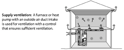
Supply ventilation, using the home’s air handler, is never operated continuously as with exhaust ventilation because the furnace or heat-pump blower is too large and would over-ventilate the home and waste electrical energy. Supply ventilation may not be appropriate for tight dwellings in very cold climates because supply ventilation can push moist indoor air through exterior walls, where moisture can condense on cold surfaces.
Motorized Outdoor-Air Damper
A motorized damper that opens when the air-handler blower operates must control outdoor-air supply. The furnace/air conditioner heats or cools the outdoor air as necessary before delivering it to the living spaces.
The damper control estimates how much ventilation air is needed. The damper closes after the required amount of ventilation air has entered during heating or cooling. The control also activates the damper and the blower for additional ventilation air as needed without heating or cooling the air during mild weather.
Supply-Ventilation System Requirements
Supply ventilation typically uses the furnace or heat pump as a ventilator. A 5-to-10 inch diameter duct connects the furnace’s main return duct to a termination outdoors.
✓ The existing duct system must leak less than 10% of the air handler flow when measured at 25 Pa. WRT outside.
✓ The outdoor air must flow through a MERV 6 or better air filter before flowing through heating and cooling equipment. See “Air Filter Effectiveness” on page 339.
✓ Ducts must conform to “Duct Materials and Installation” on page 407.
✓ Termination fittings must comply with“Termination Fittings” on page 404.
|
SWS Detail: 6.6202.2 Heat Recovery Ventilator (HRV) and Energy Recovery Ventilator (ERV) Installation, 6.6202.1 Controls |
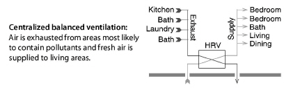
Balanced ventilation systems exhaust stale air and provide fresh air through a ducted distribution system. Of the three ventilation systems discussed here, balanced systems do the best job of controlling pollutants in the home.
Balanced systems move equal amounts of air into and out of the home. Most balanced systems incorporate heat-recovery ventilators or energy-recovery ventilators that reclaim heat and moisture from the exhaust air stream.
Balanced ventilation systems can improve the air quality and comfort of a home, but they require a high standard of care. Testing and commissioning are vital during both the initial installation and periodic service calls.
Heat-Recovery and Energy-Recovery Ventilators
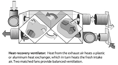
The difference between heat-recovery ventilators (HRVs) and energy-recovery ventilators (ERVs) is that HRVs transfer heat only, while ERVs transfer both sensible heat and latent heat (moisture) between air streams.
HRVs are often installed as balanced whole-building ventilation systems. The HRV core is an air-to-air heat exchanger in which the supply and exhaust air streams pass one another and exchange heat without mixing.
|
SWS Detail: 6.6207.1 Passive Ventilation (All Building Types) |
The dwelling’s residents can maintain good indoor air quality by using spot ventilation together with opening windows and doors. Depending on climate and season, residents can control natural ventilation to provide clean air, comfort, and energy efficiency.
✓ Choose windows and screen doors in strategic locations to ventilate using prevailing winds.
✓ Make sure that windows and screen doors, chosen for ventilation, open and close and have effective insect screens.
✓ Open windows to provide make-up air when an exhaust fan or the clothes dryer is operating.
✓ Understand that dust and pollen may enter through windows or screen doors and consider the consequences.
9.5.5 Rooftop-Unit (RTUs) Economizer Ventilation
Many buildings, particularly those with RTUs use economizers as their ventilation system. Economizers don’t normally have heat recovery or energy recovery function, so ventilating with an economizer can have an energy penalty compared to a heat recovery ventilators. See “Economizers” on page 332.
Mild climates are ideal for ventilating with an economizer. When buildings use an economizer for ventilation, its dampers are open a small amount while the HVAC system is heating, cooling, or operating on the fan-only option. The fan-only option is for when you need ventilation but not heating or cooling.
To run optimally, the economizer requires a programmable thermostat that tracks the amount of ventilation air delivered during the free cooling mode and during the ventilation mode. See “RTU Maintenance and Improvement” on page 333.
For information on cooling with an economizer, see “Economizers” on page 332.