Chapter 12: Air Leakage Diagnostics
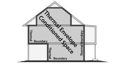
This chapter focuses on pressure-testing homes, to determine their airtightness and to guide air-sealing during weatherization. Ideally the air barrier and insulation are installed together at the building’s thermal boundary. The airtightness of the air barrier has a substantial effect on comfort, energy efficiency, and performance of the insulation. The testing described here helps to analyze the existing air barriers and decide whether and where air-sealing is needed.
12.1 Shell Air-Leakage Fundamentals
Controlling shell air leakage is a key concern for successful weatherization. The decisions you make about sealing air leaks affect a building throughout its lifespan. Air leakage has these impacts.
• Air leakage accounts for a significant percentage of a building’s heat loss.
• Air leakage through insulated assemblies reduces the R-value of insulation.
• Air leakage moves moisture in and out of the house, wetting and/or drying the building.
• Air leakage causes house pressures that can interfere with the venting of combustion appliances.
Air Leakage and Ventilation
Most homes depend on air leakage to provide outdoor air for diluting pollutants and admitting fresh air. However, air leaks can also bring pollutants into the home. Mechanical ventilation is a more reliable and efficient way to provide fresh air. See “ASHRAE Standard 62.2–2016 Ventilation” on page 395.
12.1.1 Goals of Air-Leakage Testing
Air-leakage testing accomplishes a variety of purposes.
• Air-leakage and pressure testing measures the home’s air-tightness level.
• It evaluates the home’s ventilation requirements.
• It helps you to decide how much time and effort is required to achieve cost-effective air-leakage and duct-leakage reductions.
• It helps to compare the air-tightness of the air barriers on either side of an intermediate zone, such as an attic or crawl space. For example, comparing the airtightness of the plaster ceiling with that of the ventilated sloped roof gives the auditor an idea of how leaky the ceiling is.
• It helps decide the best place to establish the air barrier in an area that has no obvious thermal boundary.
The reason for the complexity of air-leakage testing is that there is so much uncertainty about air leakage. Testing is needed because there simply is no accurate prescriptive method for determining the severity and location of leaks, especially in complex homes. Depending on the complexity of a home, you may need to perform varying levels of testing to evaluate shell air leakage. In particular, the number of major components like stories, additions, corners, and gables indicates a home’s potential for large air-leakage reductions.
Air-Sealing with Air-Leakage Testing
Dedicate most of your effort to seal the large air leaks that pass directly through the thermal boundary first. Chasing small leaks or leaks that connect to the outdoors through interior walls or floors isn’t worth as much effort if the budget is limited.
ü Perform blower door testing.
ü Analyze the test results to determine if air sealing is cost-effective.
ü Locate and seal the air leaks.
ü During air-sealing, monitor your progress with blower door testing.
ü Stop air sealing after all major bypasses have been sealed and air-sealing goals have been achieved.
12.2 Single-Family Airtightness Testing
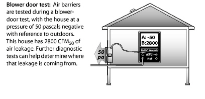
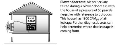
The blower door made airtightness testing for single family dwellings. The blower door measures a home’s leakage rate at a standard pressure of 50 pascals. Energy auditors use this leakage measurement to compare homes with one another and to established air-leakage standards.
The blower door also allows the auditor to test parts of the home’s air barrier to locate air leaks. Sometimes air leaks are obvious. More often, the leaks are hidden, and you need a blower door to find their location.
This section outlines the basics of blower door measurement along with some techniques for gathering clues about the location of air leaks.
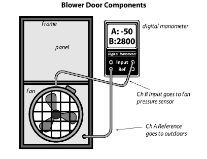
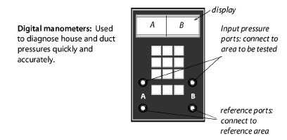
The blower door creates a 50-pascal pressure difference across the building shell and uses a manometer to measure fan pressure in order to calculate airflow in cubic feet per minute (CFM50) to estimate the leakiness of homes. The blower door also creates pressure differences between rooms in the house and intermediate zones like attics and crawl spaces. These pressure differences can give clues about the location and combined size of a home’s hidden air leaks.
Connecting the digital manometer’s hoses correctly is essential for accurate testing.
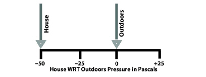
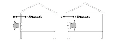
This method uses the phrase with-reference-to (WRT), to distinguish between the input zone and reference zone for a particular measurement. The outdoors is the most commonly used reference zone for blower door testing. The reference zone is considered to be the zero point on the pressure scale.
For example, house WRT outdoors = –50 pascals means that the house (input) is 50 pascals negative compared to the outdoors (reference or zero-point). This pressure reading is called the house pressure.
Low-Flow Rings
During the blower door test, the manometer measures fan pressure to calculate airflow through the fan. This airflow (CFM50) is the primary measurement of a home’s airtightness and is directly proportional to the surface area of the home’s air leaks. For the manometer to calculate airflow accurately, the airflow through the fan housing must be flowing at an adequate speed. Tighter buildings and smaller buildings don’t have enough air leakage to create an adequate airspeed to create the minimum fan pressure. This low-flow condition requires using one or two low-flow rings, to reduce the blower-door fan’s opening and to increase air speed, fan pressure, and measurement accuracy.
When the air speed is too low, the DG-700 displays “LO” in the Channel B display. After installing one of the low-flow rings, follow the manufacturer’s instructions for selecting the proper range or configuration on the digital manometer.
12.2.2 Preparing for a Blower Door Test
Preparing the house for a blower door test involves putting the house in its normal heating-season operation with all conditioned zones open to the blower door. Try to anticipate safety problems that the blower door test could cause, particularly with combustion appliances.
• Identify the location of the thermal boundary and determine which house zones are conditioned.
• Identify large air leaks that could prevent the blower door from achieving adequate pressure, such as a pet-door.
• Put the house into its heating-season operation with windows, doors, and vents closed and air registers open.
• Turn off combustion appliances temporarily.
• Open interior doors so that all indoor areas inside the thermal boundary are connected to the blower door. This could include the basement, conditioned kneewall areas, and closets.
Avoiding Risky Situations
Don’t perform a blower door test in risky situations like the following until you remove the risk or perform an acceptable building repair. Pressurization blower door testing may be done to alleviate some of these conditions.
• A wood stove or fireplace is burning.
• Loose ash is present in a fireplace or wood stove.
• Holes in the ceiling that could lead to dust pollution during a blower door test.
• Extremely weak building components, like a poorly installed suspended ceiling or loose wood wall paneling.
• Lead or asbestos dust is present.
• Urea formaldehyde foam dust is present in the building components.
12.2.3 Blower-Door Test Procedures
Follow this general procedure when performing a blower-door test.
ü Set up the house for winter conditions with exterior doors, primary windows and storm windows closed. The door to the basement should be either open or closed, according to whether or not the basement is considered to be within the thermal boundary.
ü Install blower door frame, panel, and fan in an exterior doorway with a clear path to outdoors. On windy days, install the blower door on the home’s leeward side if possible. Pay attention to the blower door’s location and any other conditions that may affect test results.
ü Follow manufacturer’s instructions for fan orientation and digital-manometer setup for either pressurization or depressurization. Depressurization is the most common orientation.
ü Connect Channel A of the digital manometer to measure house WRT outdoors. Place the outside hose at least 5 feet away from the fan.
ü Connect Channel B to measure fan WRT zone near fan inlet. Don’t place the hose directly in front of the fan intake.
ü Ensure that children, pets, and other potential interferences are at a safe distance from the fan.
Conducting the Blower Door Test
Follow these instructions for performing a blower door test, when using a DG700 digital manometer.
1. Turn on the manometer by pushing the ON/OFF button.
2. Select the MODE: PR/FL@50.
3. Select the correct DEVICE that matches the blower door you’re using.
4. With the fan covered, conduct the BASELINE procedure to cancel out the background wind and stack pressures. Let the manometer average the baseline pressure for at least 30 seconds.
5. Remove the cover from the blower door fan. Complete the next two steps for tighter buildings.
6. Install the flow ring in the blower door fan which matches the expected flow rate. The fan pressure should be at least 25 Pa while measuring CFM@50.
7. Push CONFIG or Range button until you match the flow ring being used.
8. Turn on the blower door fan slowly with the controller. Increase fan speed until the building depressurization on the Channel A screen is between –45 and –55 pascals. It doesn’t need to be exactly –50 pascals.
9. The Channel B screen will display the single-point CFM50 air leakage of the building. If this number is fluctuating a lot, push the TIME AVG button to increase the averaging time period. Do NOT push the button until the house has reached -50 pascals.
10. You can also use the cruise-control function to automatically control the fan speed to create and hold –50 pascals of pressure. For pressure diagnostics, -50 pascals is preferred.
Blower-Door Test Follow-Up
Be sure to return the house to its original condition.
ü Inspect combustion appliance pilot lights to ensure that blower door testing didn’t extinguish them.
ü Reset thermostats of heaters and water heaters that were turned down for testing.
ü Remove any temporary plugs that were installed to increase house pressure.
ü Document the location where the blower door was installed.
ü Document any unusual conditions affecting the blower door test.
12.2.4 Approximate Leakage Area
There are several ways to convert blower-door CFM50 measurements into square inches of total leakage area. A simple and rough way to convert CFM50 into an approximate leakage area (ALA) is to divide CFM50 by 10. The ALA can help you visualize the size of openings in a home or section of a home.

12.3 Multifamily Airtightness Testing
Air sealing, indoor air quality, and fire safety complement one another in multifamily buildings. Beyond sealing leaks in the exterior envelope, the most universal concept in multifamily air sealing and airtightness testing is compartmentalization. Compartmentalization means sealing the air leaks between dwelling units to provide these benefits.
• Prevent odors traveling from one dwelling unit to another.
• Prevent the rapid spread of fire and smoke from one dwelling to another.
• Save energy by sealing air leaks and reducing the stack effect.
Leak-testing multifamily buildings is considerably more difficult then testing single-family homes. A whole-building blower door test is the ideal, but is often impossible because of the huge airflow needed to pressurize the building along with the practical problems of testing a building with many occupants. These practical problems often necessitates zone testing and compartmentalization testing.
The quality and quantity of test equipment and the experience of the testing technicians determines the effectiveness of the testing. The larger the building, the more air-moving horsepower and technology the testing equipment requires.
Several software packages can automate the process of monitoring multiple blower doors and tracking pressures throughout a large building. Wireless sensors and wireless gages make the process of remote measurement more practical.
Detailed instructions about operating a large-building air-leakage testing system are beyond the scope of this field guide.
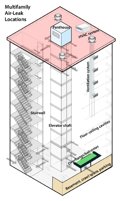
12.3.2 Multifamily Air Leakage
Energy auditors develop an air sealing strategy by evaluating the chase leakage, according to the presence and location of the following building components.
• Direct air leakage through roofs, walls, and foundations.
• Vertical chases; including stairs and elevators
• Leaks through floors allowing airflow from one floor to another.
See the following sections for more information on multifamily air leakage.
• “Weatherization Materials” on page 91
• “Air-Sealing Attics and Roofs” on page 121
• “Air Sealing Walls” on page 171
• “Air Sealing Foundations and Floors” on page 199
12.3.3 Multifamily Blower-Door-Test Strategies
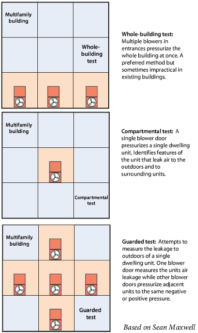
Here we discuss three different strategies for blower-door testing a multifamily building: the whole-building test, the compartmental test, and the guarded test.
Testers also measure zonal pressures to evaluate air barriers in multifamily buildings, like they do in single-family dwellings.
Whole-Building Test
Although increasingly difficult as buildings get larger, the whole-building blower door test is a preferred approach. The testers usually need multiple blower doors for this test along with an automated blower-door-testing system.
The whole-building test provides an air-leakage measurement for the entire building. Also, this blower-door test gives the best information about where the critical leaks to outdoors are located.
Compartmental Test
The compartmental test requires only one blower door. This test measures air leakage to both the outdoors and indoors.
The compartmental approach gives the energy auditor a sample of the air leaks in a single dwelling unit. The leaks in this single unit may inform the auditor about typical leaks in all dwelling units or in units with the same characteristics.
Guarded Test
Testers use the guarded test when they want to measure a single dwelling unit’s air leakage to outdoors. This test is another strategy to characterize a single unit—like the compartmental test—by only measuring leakage to outdoors. This test requires pressurizing surrounding dwelling units with the same pressure applied to the tested unit.
Zonal Pressures
Creating and measuring zonal pressures is one of the most effective ways to evaluate air leakage in multifamily buildings. Testers observe the building’s assemblies and architectural features and formulate assumptions and questions to guide their air-leakage testing and air sealing.
The testers may decide to isolate various zones and assemblies to determine their individual leakage to outdoors or to adjacent zones. The goal is a testing and air-sealing process that is cost-effective. The tests may be quantitative or qualitative. Here are some zones and assemblies that you may want to pressure-test.
• Stairwells and elevator shafts.
• Ventilation and HVAC ducts, duct joints, and duct chases.
• Overhangs and balconies.
• Basements, crawl spaces, and penthouses.
• Floor and ceiling cavities.
The next section, “Testing Air Barriers” on page 516, gives many examples of zone pressure testing.
Leaks in air barriers cause energy and moisture problems in many homes. Air-barrier leak-testing avoids unnecessary visual inspection and unnecessary air sealing in hard-to-reach areas.
Advanced pressure tests measure pressure differences between zones in order to estimate air leakage between zones. Use these tests to make decisions about where to direct your air-sealing efforts, for example.
• Evaluate the airtightness of portions of a building’s air barrier, especially floors and ceilings.
• Decide which of two possible air barriers to air seal — for example, the floor versus foundation walls.
• Determine whether building cavities like porch roofs, floor cavities, and overhangs are conduits for air leakage.
• Determine whether building cavities, intermediate zones, and ducts are connected together through air leaks.
• Estimate the air leakage in CFM50 through a particular air barrier, for the purpose of estimating the effort and cost necessary to seal the leaks.
Air-Barrier Test Results
Air-barrier tests provide a range of information from simple clues about which parts of a building leak the most, to specific estimates of the airflow and hole size through a particular air barrier.
The next table shows examples of how common building materials perform as air barriers. This information is helpful in interpreting blower door tests and selecting air-sealing materials.
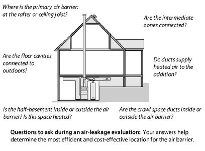
12.4.1 Primary Versus Secondary Air Barriers
A home’s air barrier should be a material that is continuous, sealed at the seams, and impermeable to airflow. Where there are two possible air barriers, in an attic for example, the most airtight barrier is the primary air barrier and the least airtight is the secondary air barrier.
The primary air barrier should be adjacent to the insulation to ensure the insulation’s effectiveness. We use pressure-diagnostic testing to verify that the insulation and the primary air barrier are together. Sometimes we’re surprised during testing to find that our assumed primary air barrier is actually secondary, and the secondary air barrier is primary.
Intermediate zones are unconditioned spaces that are sheltered within the exterior shell of the house. Intermediate zones can be located inside or outside the home’s primary air barrier. Intermediate zones include: unheated basements, crawl spaces, attics, enclosed porches, and attached garages.
Intermediate zones have two potential air barriers: one between the zone and house and one between the zone and outdoors. For example, an attic or roof space has two air barriers: the ceiling and roof. You should know which air barrier is the tightest.
Blower door tests give us valuable information about the relative leakiness of rooms or sections of the home. Listed below are five simple methods.
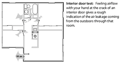
1. Feeling zone air leakage: Close an interior door partially so that there is a one-inch gap between the door and door jamb. Feel the airflow along the length of that crack, and compare that airflow intensity with airflow from other rooms, using this same technique.
2. Observing the ceiling/attic floor: Pressurize the home and observe the top-floor ceiling from the attic with a good flashlight. Air leaks will show in movement of loose-fill insulation, blowing dust, moving cobwebs, etc. You can also use a small piece of tissue paper or smoke generator to disclose air movement. An infrared camera also works well for identifying leakage areas during heating and cooling seasons.
3. Observing smoke movement: Pressurize the home and observe the movement of smoke through the house and out of its air leaks.
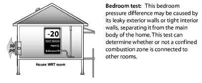
4. Room pressure difference: Check the pressure difference between a closed room or zone and the main body of a home. Larger pressure differences indicate larger potential air leakage within the closed room or else a tight air barrier between the room and main body. A small pressure difference means little leakage to the outdoors through the room or a leaky air barrier between the house and room.
5. Room airflow difference: Measure the house CFM50 with all interior doors open. Close the door to a single room, and note the difference in the CFM50 reading. The difference is the approximate leakage through that room’s air barrier.
Tests 1, 2, and 3 present good client education opportunities. Feeling airflow or observing smoke are simple observations, but have helped identify many air leaks that could otherwise have remained hidden.
When airflow within the home is restricted by closing a door, as in tests 4 and 5, it may take alternative indoor paths that render these tests somewhat misleading. Only practice and experience can guide your decisions about the applicability and usefulness of these general indicators.
12.4.3 Simple Zone Pressure Testing
Manometers aren’t limited to finding indoor WRT outdoor differences. They can also measure pressure differences between the house and its intermediate zones during blower-door tests. The purpose of these tests is to evaluate the air-tightness of the home’s interior air barriers.
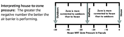
The blower door, when used to create a house-to-outdoors pressure of –50 pascals, also creates house-to-zone pressures of between 0 and –50 pascals in the home’s intermediate zones. The amount of depressurization depends on the relative leakiness of the zone’s two air barriers.
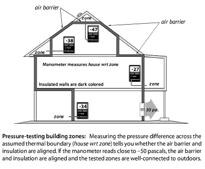
For example, in an attic with a fairly airtight ceiling and a well-ventilated roof, the attic will indicate that it is mostly outdoors by having a house-to-zone pressure of –45 to –50 pascals. The leakier the ceiling and the tighter the roof, the smaller that the negative house-to-zone pressure will be. This holds true for other intermediate zones like crawl spaces, attached garages, and unheated basements.
Zone Leak-Testing Methodology and Diagnostics
Depressurize house to –50 pascals with a blower door.
1. Find an existing hole, or drill a hole through the floor, wall, or ceiling between the conditioned space and the intermediate zone.
2. Connect the reference port of a digital manometer to a hose reaching into the zone.
3. Leave the input port of the digital manometer open to the indoors.
4. Read the negative house to zone pressure given by the manometer.
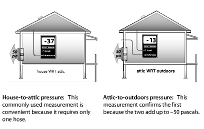
5. Readings of negative 25-to-50 pascals house-to-attic pressure mean that the ceiling is tighter than the roof. If the roof is almost completely airtight, achieving a 50-pascal house-to-attic pressure difference may be difficult. However if the roof is well-ventilated, achieving a near-50-pascal difference should be possible.
6. Readings of negative 0-to-25 pascals house-to-attic pressure mean that the roof is tighter than the ceiling. If the roof is well-ventilated, the ceiling has even more leakage area than the roof’s vent area.
7. Readings around –25 pascals house-to-attic pressure indicate that the roof and ceiling are equally airtight or leaky.
8. For an estimation of your target for air sealing, See “Pressure Diagnostics – Hole Size Ratios” on page 535.
9. Air sealing should be performed as necessary, until the pressure is as close to –50 pascals as possible.
10. The thermal boundary and air barrier are to be continuous and in alignment with each other.
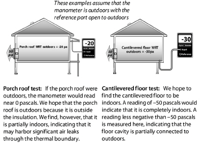
Leak-Testing Building Cavities
Building cavities such as wall cavities, floor cavities between stories, and dropped soffits in kitchens and bathrooms can also be tested as described above to determine their connection to the outdoors as shown here.
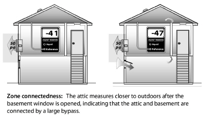
Testing Zone Connectedness
Sometimes it’s useful to determine whether two zones are connected by a large air leak. Measuring the house-to-zone pressure during a blower door test, before and then after opening the other zone to the outdoors, can establish whether the two zones are connected by a large air leak. You can also open an interior door to one of the zones and check for pressure changes in the other zone.
Leak-Testing Building Cavities
You can also test building cavities such as wall cavities, floor cavities between stories, and dropped soffits in kitchens and bathrooms with a digital manometer to evaluate their possible connection to the outdoors by way of air leaks.