Chapter 8: Heating and Cooling Systems
This chapter discusses safety and energy-efficiency improvements to heating and cooling systems. It is divided into these main sections.
1. Essential combustion-safety testing
2. Heating-system replacement
3. Servicing gas and oil heating systems
4. Combustion venting
5. Heating distribution systems
6. Air-conditioning systems
The SWS requires that weatherization agencies perform a combustion-safety evaluation as part of each weatherization work scope. This evaluation is the chapter’s second topic. The chapters other topics are procedures and requirements related to cost-effective ECMs, such as tune-ups and equipment replacement.
Qualified heating technicians should perform the installations, adjustments, and maintenance described in this chapter.
Important Note: Use manufacturer’s specifications and instructions whenever they are available. Many of the specifications in this chapter assume that the manufacturer’s instructions aren’t available. In the absence of manufacturer’s specifications, we offer specific guidance that experts and reviewers consider correct.
8.1 HVAC-System Commissioning & Education
HVAC commissioning is the process of inspecting, testing, a system and educating occupants, landlords, and building operators to achieve the following goals.
8.1.1 HVAC-System Commissioning
|
SWS Details: 5.3102.38 Full Commissioning,5.3003.6 Evaluating Sequence of Operation, 5.3002.12 Cooling Equipment—Installation, Maintenance, and Commissioning— Mid and High Rise |
ü Verify that the HVAC system works as the manufacturer, designer, and installer understand that it should work, based on plans, specifications, and manufacturers’ literature.
ü Take appropriate measurements to verify that the HVAC system works safely and efficiently.
ü Verify that the building owner or building operator understands the HVAC system’s operation and has the necessary system documentation.
ü Verify that the building owner or building operator understand the procedures and schedule for routine maintenance.
There are three (3) types of commissioning.
1. Retro-commissioning, is commissioning implemented on existing HVAC equipment in an existing building.
2. Initial commissioning occurs during installation of a new HVAC system.
3. Re-commissioning is commissioning HVAC systems, that were already commissioned during original HVAC-system installation.
This chapter strives to provide the essential information for commissioning HVAC systems. However, this information isn’t a substitute for plans, specifications, and manufacturers’ literature that should guide all HVAC installations.
8.1.2 Multi-Family HVAC-System Education
Multi-family buildings are complex systems of building envelopes and mechanical systems that harbor a variety of hazards. Educate occupants, landlords, and building operators about the health and safety hazards and the improvements that you make to mitigate these hazards.
ü Explain equipment operation and maintenance (O&M).
ü As appropriate, provide a O&M procedures manuals and manufacturers’ equipment specifications. Encourage occupants or staff to store important documents in a safe and obvious location.
ü Instruct occupants or staff to remove combustible materials from near ignition sources.
ü Inform occupants and staff about smoke alarms, carbon monoxide (CO) alarms, and combination alarms, and explain their functioning.
8.2 Combustion-Safety Evaluation
|
SWS Detail: 2.0103.1 Combustion Worker Safety, 5.3003.14 Combustion Analysis of Gas-Fired Appliances (LP and Natural Gas), 5.3003.2 Combustion Analysis of Oil-Fired Appliances |
Combustion safety will be evaluated prior to shell work being performed, after each day of shell work, and upon final inspection at the completion of the job.
8.2.1 Combustion-Safety Observations
Make the following observations before testing to help you determine the likelihood of carbon monoxide (CO) and spillage problems.
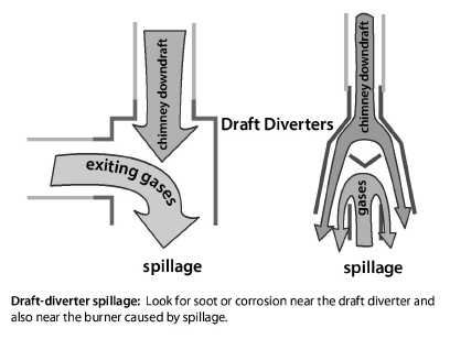
ü Recognize soot near the draft diverter, barometric damper, or burner of a combustion appliance as a sign that the appliance produces CO and spills combustion gases.
ü Recognize that rust in a chimney or vent connector may also indicate spillage.
ü Look for leaks, disconnections, and blockages in the venting system.
ü Specify that workers seal all accessible return-duct leaks near combustion furnaces.
ü Verify that the home has a working CO alarm. If the home has no working smoke alarm in addition to no CO alarm, install a combination CO-smoke alarm, or separate CO and smoke alarms. See also "Smoke and Carbon Monoxide (CO) Alarms" on page 26.
ü Inspect gas ovens and range burners for flame stability and test them for carbon monoxide. See "Gas Range and Oven Safety" on page 28.
ü Evaluate combustion air requirements for all combustion appliances. If the equipment is lacking available combustion and ventilation air per National Fuel Gas Code (NFPA 54) make necessary modifications. Note: If combustion and ventilation air requirements are met, worst case draft testing and combustion analysis must still be performed to evaluate the effects of depressurization on the appliances.
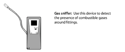
Natural gas and propane piping systems may leak at their joints and fittings. Find gas leaks with an electronic combustible-gas detector, also called a gas sniffer. A gas sniffer finds significant gas leaks if used correctly.
ü Sniff all valves and joints with the gas sniffer.
ü Accurately locate leaks using a noncorrosive bubbling liquid, designed for finding gas leaks.
ü Repair all gas leaks or label them for a gas service person to repair.
ü Replace kinked, cracked, or corroded flexible gas connectors.
ü Replace flexible gas lines manufactured before 1973. The line’s manufacture date is stamped on a date ring attached to the flexible gas line or on the body of the hex nut. If a date ring isn’t present and you believe the gas line predates 1973, then replace the flexible gas line.
8.2.3 Carbon Monoxide (CO) Testing
|
SWS Detail: 2.0103.1 Combustion Worker Safety,2.0201.2 2.0201.1 Combustion Appliance Zone (CAZ) Testing, 2.0301.2 Carbon Monoxide Alarm or Monitor |
CO testing is essential for evaluating the safety of combustion and venting. Measure CO in the flue gas of every combustion appliance you inspect and service. Measure CO in ambient air in both the home and CAZ as part of inspection and testing of combustion appliances. We strongly recommend using a full-featured electronic combustion analyzer for flue-gas analysis during this essential combustion safety testing. See “Critical Combustion-Testing Parameters” on page 274.
Vent Testing for CO
Testing for CO in the appliance vent is a part of combustion testing that happens under worst-case conditions. CO production in the undiluted combustion byproducts should not exceed the following limits.
• Vented space heaters and water heaters: 100 ppm as measured or 200 ppm air-free.
• Furnaces or boilers: 100 ppm as measured or 200 ppm air-free. Maximum allowable CO level is 200 PPM as-measured or 400 PPM air-free but only after all reasonable attempts have been made to reduce CO production. See “Carbon Monoxide (CO) Testing” on page 254.
• For oven and range burners See “Gas Range and Oven Safety” on page 28.
Ambient Air Monitoring for CO
The DOE SWS require CO monitoring during combustion testing to ensure that CO in the combustion appliance zone (CAZ) doesn’t exceed dangerous levels.
ü If ambient CO level in the CAZ exceeds 70 ppm, stop testing for your own safety. Communicate the situation clearly to the client, immediately evacuate the home, and contact appropriate personnel.
ü If ambient CO level in the CAZ exceeds 35 ppm, but is less than 70 ppm, communicate the issue clearly and immediately to the client and suggest appropriate solutions. Exam appliances for signs of damage, misuse, improper repairs, and lack of maintenance.
ü Ventilate the CAZ thoroughly before resuming combustion testing.
ü Investigate indoor CO levels (which are greater than outdoor ambient levels) to determine their cause. See "Causes of Carbon Monoxide (CO)" on page 25.
8.2.4 Worst-Case CAZ Depressurization Testing
|
SWS Detail: 2.0103.1 Combustion Worker Safety 2.0201.1 2.0201.3 Vented Combustion Appliance Safety Testing, Combustion Appliance Zone (CAZ) Testing, 2.0201.2 Combustion Safety - Make-up Air |
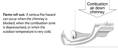
CAZ depressurization is the leading cause of backdrafting and flame roll-out in furnaces and water heaters that vent into naturally drafting chimneys and venting systems.
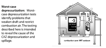
Worst-case depressurization testing uses the home’s exhaust fans, air handler, and chimneys to create worst-case depressurization in the CAZ. During this worst-case testing, you measure the CAZ pressure difference with reference to (WRT) outdoors and test for spillage.
Worst-case conditions do occur, and venting systems must exhaust combustion byproducts even under these extreme conditions. Worst-case vent testing exposes whether or not the venting system exhausts the combustion gases when the combustion-zone pressure is as negative as you can make it. A digital manometer is the best tool for accurate and reliable readings of combustion-zone depressurization.
Take all necessary steps to reduce CAZ depressurization and minimize combustion spillage, based on your tests.
Worst-Case CAZ Depressurization Test
Follow the steps below to find the worst-case depressurization level in the combustion appliance zone (CAZ).
1. Turn off or set to pilot all vented combustion appliances.
2. Close all exterior doors, windows, and fireplace damper(s). Open all interior doors, including closet doors.
3. Turn off all operating exhaust appliances including clothes dryers and occupant ventilation fans.
4. Remove furnace filter. Be sure the filter slot is covered for the test.
5. Record the baseline pressure of the CAZ with reference to outdoors.
6. Turn on the clothes dryer and exhaust fans. (Clean clothes dryer filter.)
7. Open interior doors to negative-pressure zones (rooms with exhaust fans) and close doors to all other rooms off the main body. Use smoke or a manometer to verify room pressures across doors that separate sections of the main body or to a door you are just not sure about. Position doors to create the greatest negative pressure in the CAZ.
8. Open and close the CAZ door. Record the most negative pressure and note CAZ door position.
9. Turn on the furnace air handler. Reposition interior doors as appropriate. Smoke or pressure test doors to rooms with exhaust fans, returns or doors that you are not sure about. Position doors accordingly.
10. Open and close the CAZ door. Record the most negative pressure, and note CAZ door position.
11. Calculate the net difference between the worst depressurization found from either #6 or #8 and the baseline pressure from #3. This is the worst-case depressurization.
12. CAZ depressurization levels should be evaluated carefully. Be suspicious if CAZ levels are more negative than -2 and particularly when -3 or greater and the appliances appear to function properly. Make sure wind is not helping the combustion appliances to vent. CAZ testing is best done on calm days.
13. Use the following troubleshooting chart to assist in specifying appropriate improvements when combustion appliances back-draft or do not function properly when tested under worst case.
14. Auditors - Use the House Depressurization chart in Appendices to help predict potential post-Wx depressurization levels. See “House Depressurization Chart” on page 536.
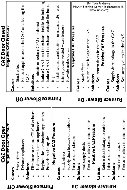
Analyzing CAZ Depressurization
Analyze the negative and positive pressures you measure in the CAZ to find workable solutions, using the troubleshooting table here.
Next, verify that the combustion gases don’t spill or contain excessive CO at worst-case depressurization. Test each appliance in turn for spillage and CO as described below.
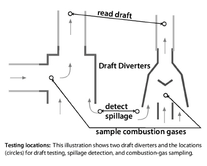
1. Check for flue-gas flow in the venting system. Feel the vent connector for heat. The vent connector should start warming within 5 seconds if it establishes flue-gas flow. If the vent connector remains cold, stop the test and investigate.
2. Detect spillage at the draft diverter of each combustion appliance in one of these ways.
a. Smoke from a smoke generator is repelled by spillage at the draft diverter.
b. A mirror fogs from spillage at the draft diverter
3. If spillage in one or more appliances continues at worst-case depressurization for 2 minutes or more, take action to correct the problem.
4. Measure and record vent pressure in each category 1 appliance after 5 minutes.
5. Measure and record vent pressure in each category 1 appliance after 5 minutes.
6. Measure CO in the undiluted flue gases of each vented space heater or water heater after 5 minutes of operation at worst-case depressurization. If CO in undiluted flue gases is more than 100 ppm as measured or 200 ppm air-free measurement, take action to reduce CO level.
7. Measure CO in the undiluted flue gases of each furnace or boiler after 5 minutes of operation at worst-case depressurization. If CO in undiluted flue gases is more than 100 ppm as measured or 200 ppm air-free measurement, take action to reduce CO level. Maximum allowable CO in undiluted flue gases is 200 PPM as-measured or 400 PPM air-free but only after all reasonable attempts have been made to reduce CO production.
8.2.5 Evaluating Combustion Air
|
SWS Detail: 2.0203.1 Combustion Air for Natural Draft Appliances |
Combustion appliances need an air supply to support combustion and to balance the draft in natural-draft chimneys. In most buildings, combustion air comes through the building’s air leaks.
If workers seal the building tightly, they may reduce the available combustion air to a level that causes combustion problems. Evaluate combustion air using the following guidance.
8.2.6 Combustion and Ventilation Air
|
SWS Detail: 2.0203.1 Combustion Air for Natural Draft Appliances |
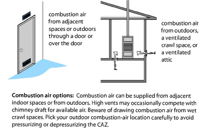
A combustion appliance zone (CAZ) is the space or room containing the combustion appliances. Evaluate all CAZs to determine whether proper combustion and ventilation air is available. Combustion air is supplied to the combustion appliance one of four ways.
1. To the CAZ directly through air leaks in the building.
2. To the CAZ through an intentional opening or openings between the CAZ and other indoor areas where air leaks replenish combustion air.
3. To the CAZ through intentional openings to the outdoors or ventilated intermediate zones like attics or crawl spaces.
4. Directly from the outdoors to the appliance. Appliances with direct combustion air supply are called direct-vent or sealed-combustion appliances.
Important Note: The National Fuel Gas Code presents two methods for calculating combustion air. The simpler of the two methods is The Standard Method. Apply the Standard Method when air leakage rate of the CAZ or house is sufficient. To use interior air for combustion and ventilation, the estimated natural air infiltration rate of the building must be no less than 0.4 ACH. If the air-leakage rate of the CAZ or structure is insufficient, then comply with the combustion and ventilation air requirements using the KAIR (Known Air Infiltration Rate) method per NFPA 54. However, neither method really predicts the amount of available combustion air due to the effects of exhaust fans and pressure imbalances from air handler operation. Perform a comprehensive worst case CAZ depressurization test as described in “Worst-Case CAZ Depressurization Testing” on page 255 to evaluate the combustion safety of the system.
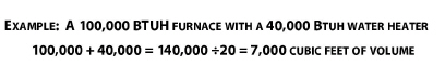
The Standard Method for determining the minimum volume communicating with the combustion appliances is 50 cubic feet of volume per 1000 BTUH of appliance input. This is sometimes referred to as the 1/20th rule. Required volume equals the total BTUH input of the appliances in the CAZ divided by 20.
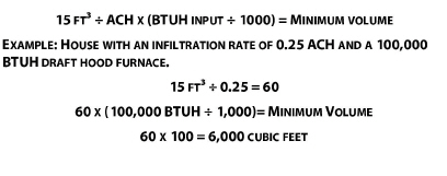
8.2.8 Known Air Infiltration Rate (KAIR) Method
If you know the air infiltration rate of the structure, determine the minimum volume communicating with the CAZ by applying the infiltration rate to the calculation detailed in the NFPA 54. There are two equations for this method, one is for fan-assisted appliances and one is for draft-hood-type appliances.
Other than Fan Assisted Calculation
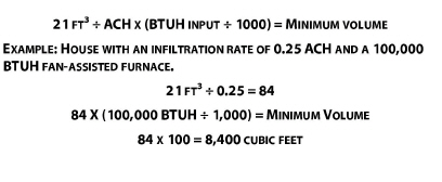
Fan-Assisted Calculation:
8.2.9 Connecting Indoor Spaces
If the CAZ volume is less than the minimum, you may connect the CA to the adjacent space with combustion-air openings sized and located in accordance with the following table.
|
Location |
Dimensions |
|
Combining spaces on the same story: Two openings, 1 within 12 inches of the top of the enclosure and 1 within 12 inches of the bottom of the enclosure |
Minimum free area: 1 in² per 1000 Btuh with a minimum of 100 in² |
|
Combining spaces in different stories: One or more openings in doors or floors |
Minimum free area: 2 in² per 1000 Btuh Input |
Louvers and Grilles
Where louver and grille design and free area are not know, it shall be assumed that metal louvers have 75 percent free area and wood louvers have 25 percent free area.
8.2.10 Combustion Air from Outdoors
If the air leakage rate or the volume of the structure is determined to be insufficient, then outdoor combustion and ventilation air shall be provided through opening(s) to the outdoors.
• Combustion air from outdoors should only be added if the CAZ can be isolated from the rest of the dwelling.
• Consider mechanical combustion air systems when adding passive air openings from outdoors is impractical.
The openings used shall be sized and located in accordance with the following:
|
Location |
Dimensions |
|
Two direct vertical ducts to outdoors, 1 commencing within 12 inches of the top of the enclosure and 1 within 12 inches of the bottom of the enclosure |
Minimum free area: 1 in² per 4000 BTUH input for each opening |
|
Two direct horizontal ducts to outdoors, 1 commencing within 12 inches of the top of the enclosure and 1 within 12 inches of the bottom of the enclosure |
Minimum free area: 1 in² per 2000 BTUH input for each opening |
|
Single direct horizontal or vertical opening or duct to outdoors commencing within 12 inches of the top of the enclosure. |
Minimum free area: 1 in² per 3000 BTUH input and not less than the sum of the areas of all vent connectors in the space |
Evaluating Combustion Air by Flue-Gas Analysis
Make-up air required for the operation of exhaust appliances needs to be considered when determining the adequacy of a space to provide combustion air.
• Per NFPA 54 2012: “Where exhaust fans, clothes dryers, and kitchen ventilation systems interfere with the operation of appliances, make-up air shall be provided.”
• Combustion analysis can be performed under natural conditions to assist in determining the adequacy of combustion air in the space.
• When exhaust fans are operating, combustion analysis can be used to determine if the operation of the appliances is affected.
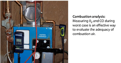
During worst-case testing, use a combustion analyzer to measure both CO and oxygen (O2). See “Critical Combustion-Testing Parameters” on page 274.
The O2 is an indicator of excess combustion air, and high CO may be an indicator of insufficient combustion air.
1. Sample undiluted flue gases as they leave the appliance’s heat exchanger during worst-case conditions.
2. If the O2 reading from the combustion analyzer is more than 5% with a natural-draft burner or more than 3% with a power burner or well adjusted and maintained barometric draft control, combustion air is probably adequate if CO is minimal.
3. If the O2 reading from the combustion analyzer is less than the above O2 values, this indicates that combustion air is inadequate or that the appliance is over-fired. We would expect significant CO to accompany such low O2 readings.
4. If O2 is too low, measure fuel input to verify that the firing rate is at or below the manufacturer’s BTUH specifications for input.
5. If O2 is too low at the correct firing rate, open a door or a window connected to the CAZ. If opening the CAZ door, a nearby window, an exterior door, or any combination of these increases the O2 reading and decreases CO, then consider the options specified in “Combustion-Air-Related Solutions” on page 269.
8.2.11 Mitigating CAZ Depressurization and Spillage
If you find problems with CAZ depressurization or spillage, consider the following to determine the cause.
1. Set the dwelling to natural conditions. If the spillage disappears, the problem is depressurization. If the spillage persists, the problem will either be combustion air or a vent problem.
2. Open a window or exterior door. If spillage disappears, the problem will be combustion air. If the spillage persists, the problem will be with the vent.
Improvements to Mitigate CAZ Depressurization
If spillage is a result of depressurization, the problem will be a lack of make-up air for exhaust fans, duct leakage or door closure.
This list of improvements may solve spillage problems detected during the previous tests on a forced air heating system.
ü Seal all supply ducts exterior to the dwelling.
ü Address pressure imbalances due to interior door closure.
ü Seal all return-duct leaks in the CAZ or near the furnace.
ü Isolate combustion appliances from exhaust fans, clothes dryers, and return registers by air sealing between the CAZ and zones containing these depressurizing devices as described on page 269.
ü Replace the appliances with sealed-combustion or direct vent units capable off withstanding the depressurization in the CAZ.
ü Reduce the CFM of exhaust appliances or eliminate unnecessary exhaust fans.
The addition of a passive combustion air opening to the exterior intended to address a make-up air problem is not allowed.
|
Problem |
Possible Solutions |
|---|---|
|
Spills immediately and continuously |
Remove chimney blockage, seal chimney air leaks, or provide additional combustion air as necessary. |
|
Exhaust fans cause spillage |
Isolate the CAZ or replace the appliances with depressurization resistant units. |
|
Blower activation causes spillage |
Provide pressure relief for balancing the air flow in the dwelling or seal ducts as appropriate. |
Chimney Improvements to Mitigate Spillage Problems
Suggest the following chimney improvements to mitigate spillage problems, detected during the previous testing.
• Remove chimney obstructions.
• Repair disconnections or leaks at joints and where the vent connector joins a masonry chimney.
• Measure the size of the vent connector and chimney and compare to vent-sizing information listed in Chapter 13 of the National Fuel Gas Code (NFPA 54). A vent connector or chimney liner that is either too large or too small can cause spillage.
• If wind causes spillage, install a wind-dampening chimney cap.
• If heat and moisture have deteriorated the masonry chimney, install a new chimney liner.
• Increase the pitch of horizontal sections of vent, if the pitch is less than 1 inch per foot.
• Increase the vertical rise of the vent connector, directly off the appliance vent fitting.
• Replace a single-wall vent connector with a double-wall vent connector.
Fixing Persistent Depressurization and Spillage Problems
Sometimes buildings and their combustion appliances don’t respond to the possible solutions listed previously. For persistent depressurization, spillage, and make-up air consider the following solutions.
• Replace open combustion appliances with sealed-combustion appliances.
• For an orphaned water heater either reline the chimney with a correctly sized chimney liner or replace gas or oil-fired water heaters with direct vent, sealed combustion, power vent, on-demand or electric water heaters.
• If opening the CAZ door reduces worst-case CAZ depressurization, consider providing a vent between the CAZ and surrounding zones.
8.2.12 Combustion-Air-Related Solutions
If previously mentioned solutions are inadequate, consider replacing open-combustion appliances with sealed-combustion appliances. The options discussed here have a risk of failure because of the unknowns with installing supplemental combustion air and isolating CAZs from the remainder of the building. Sealed-combustion is the ultimate answer to the problems of combustion air, depressurization, and spillage. For complete combustion and ventilation air requirements see “Evaluating Combustion Air” on page 261.
Installing Supplemental Combustion Air
Combustion-air vents should be no less than 3 inches in their smallest dimension. A vent with a louver or grille has a net free area (NFA) that is smaller than actual vent area because NFA accounts for the blocking effect of louvers and grilles. Metal grilles and louvers provide about 75% of their area as net-free area while wood louvers provide only about 25%.
If testing indicates the need for supplemental combustion air, install openings to one of these places.
• Another indoor space
• A ventilated intermediate zone, such as a ventilated attic or ventilated crawl space
• From outdoors into an isolated CAZ.
• From outdoors to the appliance by replacing natural-draft combustion appliances with sealed-combustion (direct-vent) appliances.
After installing supplemental combustion air, repeat the worst-case testing to verify that the combustion air problem is solved and that the combustion is safe.
Zone Isolation for Natural-Draft Vented Appliances
If replacing natural-draft appliances with sealed-combustion isn’t an option, isolating the CAZ improves the safety of natural-draft vented appliances in some cases. The CAZ is isolated if it receives combustion air only from outdoors or a ventilated intermediate zone. Inspect the CAZ for connections with the home’s main zone and seal all connections.
1. Seal all connections between the isolated CAZ and the home. Examples include joist spaces, transfer grills, leaky doors, and holes for ducts or pipes.
2. Measure a base pressure from the CAZ to outdoors.
3. Set-up house in worst case, and verify that the set-up doesn’t affect the CAZ pressure.
4. Measure CO and O2 at worst-case and evaluate combustion air as described in “Evaluating Combustion Air by Flue-Gas Analysis” on page 265.
5. If the CAZ-to-outdoors pressure changed during worst-case, continue to air-seal the CAZ, and retest as described in steps #2 and #3.
6. If the zone isolation fails, replace natural-draft appliances with sealed-combustion appliances.
8.3 Electronic Combustion Analysis
|
SWS Detail: 5.3003.2 Combustion Analysis of Oil-Fired Appliances, 2.0201.2 Combustion Safety - Make-up Air, 5.3003.14 Combustion Analysis of Gas-Fired Appliances (LP and Natural Gas) |
The goal of a combustion analysis is to analyze combustion safety and efficiency. When the combustion appliance reaches steady-state efficiency (SSE), you can measure its most critical combustion parameters. This information saves time and indicates what adjustments the service tech should make.
Modern combustion analyzers measure O2, CO, and flue-gas temperature. Some models also measure draft. Combustion analyzers also calculate combustion efficiency or steady-state efficiency (SSE) (two terms that mean the same thing).
8.3.1 Critical Combustion-Testing Parameters
These furnace-testing parameters tell you how efficient and safe a combustion appliance currently is and how much you might be able to improve its efficiency. Use these measurements to analyze the combustion process.
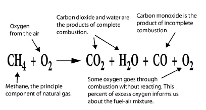
Carbon monoxide (CO) (ppm):
Poisonous gas indicates incomplete combustion. Modern combustion analyzers let you choose between an as-measured value or a calculated value that states the concentration of CO in theoretical air-free flue gases. Adjusting combustion to produce less than 100 ppm as measured or 200 ppm air-free is almost always possible with fuel-pressure adjustments, air adjustments, or burner maintenance.
Oxygen (percent):
Indicates the percent of excess air and whether fuel-air mixture is within a safe and efficient range. Combustion efficiency or SSE increases as oxygen decreases because excess air, indicated by the O2 carries heat up the chimney. Percent O2 may also indicate the cause of CO as either too little or too much combustion air. Technicians used to measure CO2, but O2 is easier to measure, and you only need to measure one of these two gases.
Flue-gas temperature:
Flue-gas temperature is directly related to combustion efficiency or SSE. Too high flue-gas temperature wastes energy and too-low flue-gas temperature causes corrosive condensation in the venting system.
Smoke number
For oil only, this measurement compares the stain made by flue gases with a numbered stain-darkness rating called smoke number. Smoke number should be 1 or lighter on a 1-to-10 smoke scale.
Draft
The pressure in the chimney or vent connector (chimney draft or breech draft). Also the pressure in the combustion chamber (over-fire draft), used primarily with oil power burners.
8.4 Heating System Replacement
|
SWS Detail: 2.0702 Installed Equipment, 2.0103.1 Combustion Worker Safety, 5.3101.1 Heat Load Calculation—Whole House |
This section discusses replacing combustion furnaces and boilers. We’ll also discuss gas heating-replacement and oil-heating-replacement specifications.
See “HVAC-System Commissioning” on page 250. See “Multi-Family HVAC-System Education” on page 251.
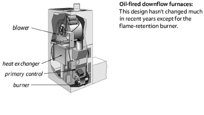
8.4.1 Furnace or Heat Pump Replacement
This section discusses air handlers of combustion furnaces and also heat pumps. Successful air-handler replacement requires selecting the right heating (and cooling) input, blower model, and blower speed. The installation must include making repairs to ducts and other remaining components, and testing to verify that the new air handler operates correctly.
Preparation for Replacement
ü Recover refrigerant in the existing heating-cooling unit according to EPA regulations.
ü Disconnect and remove the furnace or heat pump, attached air-conditioning equipment, and other materials that won’t be reused.
ü Transport these materials off the client’s property to a recycling facility.
ü Verify that all accessible ducts were sealed as part of the furnace’s installation, including the air handler, the plenums, and the branch ducts.
Equipment Selection
ü Evaluate the building to determine the correct size of the furnace or heat pump, using ACCA Manual J or equivalent method. Manual J calculations for heating and cooling (in the case of heat pump replacement) are required to be in the completed client file.
ü Select the smallest BTUH output furnace that exceeds your heat loss calculation and that your preferred manufacturer offers.
ü Select the heating/cooling equipment using ACCA Manual S or equivalent method along with manufacturers’ air-handler specifications. Consider blower airflow requirements for air conditioning (in addition to heating) if the new unit includes central air conditioning.
ü Select the supply and return registers using ACCA Manual T or equivalent method.
ü Ducts should be sized using ACCA Manual D or equivalent.
Air-Handler Installation
ü Install MERV 6 or higher filter inside or outside of the new air handler. MERV 6 filters are not required for existing site-built furnaces or any mobile home furnaces.
ü The filter must be easy to replace and in a user friendly location.
ü The filter retainer must hold the filter firmly in place and must have a cover if a filter slot exists.
ü The filter must provide complete coverage of blower intake or return grille. The filter housing and restraint must not permit air to bypass the filter.
ü If flue-gas temperature or supply air temperature are unusually high, check static pressure, fuel input, or electrical input. See “Ducted Air Distribution” on page 322.
ü Attach the manufacturer’s literature, including operating manual and service manual, to the furnace or heat pump.
Supporting Air Handlers
Support the new air handlers using these specifications.
• Support horizontal air handlers from below with a non-combustible, water-proof, and non-wicking material. Or support the horizontal air handler with angle iron and threaded rod from above.
• Support upflow air handlers with corner support legs, bricks, or pads from below when necessary to hold it above a damp basement floor.
• Support downflow air handlers with a strong, airtight supply plenum. Insulate this supply plenum to minimize energy loss.
8.4.2 Gas-Fired Heating Installation
|
SWS Detail: 2.0201.2 Combustion Safety - Make-up Air, 5.3003.14 Combustion Analysis of Gas-Fired Appliances (LP and Natural Gas), 2.0702 Installed Equipment |
The goals of gas-appliance replacement are to save energy and improve heating safety. The heating replacement project should produce a gas-fired heating system in virtually new condition, even though existing components like the gas lines, chimney, pipes, or wiring may remain.
Include maintenance, repair, or replacement of existing components as part of the installation. Analyze design defects in the original system, and correct the defects during the heating system’s replacement.
• If possible, install a condensing sealed-combustion (direct vent) furnace or boiler with a 90+ AFUE.
• Install new gas-fired unit with adequate clearances to allow maintenance.
• Follow the manufacturer's installation instructions along with the National Fuel Gas Code (NFPA 54) to ensure a proper installation.
• To help ensure compliance with Indiana Wx standards, Indiana's New Furnace Installation Inspection form must be completed prior to the start of shell work on the dwelling. The completed form is to be included in the client file.
Testing New Gas-Fired Heating Systems
ü Do a combustion test, and adjust fuel-air mixture to minimize O2. However don’t allow CO beyond 100 ppm as measured or 200 ppm air-free with this adjustment. See page 254.
ü Verify that the gas water heater vents properly after installation of a sealed-combustion or horizontally vented furnace or boiler. Install a chimney liner if necessary to provide right-sized venting for the water heater.
8.4.3 Combustion Boiler Replacement
|
SWS Details: 2.0103.1 Combustion Worker Safety, 5.3001.1 Load Calculation and Equipment Selection, 5.3101.2 Space Load Calculation—Heat Emitter Sizing, 2.0702 Installed Equipment |
Technicians replace boilers as an energy-conservation measure or for health and safety reasons.
Boiler piping and controls present many options for zoning, boiler staging, and energy-saving features. Dividing homes into zones, with separate thermostats, can significantly improve energy efficiency compared to operating a single zone.
Follow these specifications when recommending a replacement boiler.
Design
A boiler’s seasonal efficiency is more sensitive to correct sizing compared to a furnace.
ü Determine the correct size of the boiler, using ACCA Manual J and considering the installed radiation surface connected to the boiler.
ü Consider weatherization work that reduced the heating load serviced by the previous boiler when sizing the new boiler.
ü Size new radiators according to room heat loss and design water temperature.
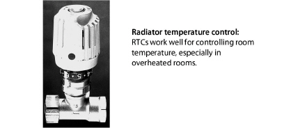
ü Specify radiator temperature controls (RTCs) for areas with a history of overheating.
ü A functioning pressure-relief valve, expansion tank, air-excluding device, back-flow preventer, and an automatic fill valve must be part of the new hydronic system.
Pump and Piping
ü Verify that all supply piping is insulated with foam or fiberglass pipe insulation.
ü Suggest that the pump be installed near the downstream side of the expansion tank to prevent the suction side of the pump from depressurizing the piping, which can pull air into the piping system.
ü Replace the expansion tank, unless it’s the correct size for the new system. Adjust the expansion tank for the correct pressure during boiler installation. See page 358.
ü Extend new piping and radiators to conditioned areas, like additions and finished basements, which are currently heated by space heaters.
Controls
ü Maintaining a low-limit boiler-water temperature is wasteful. Boiler controls should cold-start the boiler, unless the boiler is used for domestic water heating.
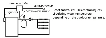
ü For large boilers, install reset controllers that adjust supply water temperature according to outdoor temperature and prevent the boiler from firing when the outdoor temperature is a sufficient temperature so that heat isn’t needed.
ü Verify that return-water temperature is above 130° F for gas and above 150° F for oil, to prevent acidic condensation within the boiler, unless the boiler is designed for condensation. Install piping bypasses, mixing valves, primary-secondary piping, or other strategies, as necessary, to prevent condensation within a non-condensing boiler.
Combustion Testing
ü Inspect the chimney and upgrade it if necessary.
ü Verify that flue-gas oxygen and temperature are within the ranges specified in these two tables.
a. “Combustion Standards for Gas Furnaces and Boilers” on page 275
b. “Minimum Oil Burner Combustion Standards” on page 298
Steam Boilers
Steam-boiler performance depends heavily on the adequacy of the existing steam distribution system. The boiler installer should know how the distribution system performed when it was connected to the old boiler.
The new boiler’s water line should be at the same height as the old boiler’s water line, or the installers should know how to compensate for the difference in water-line levels. See "Steam Heating and Distribution" on page 361.
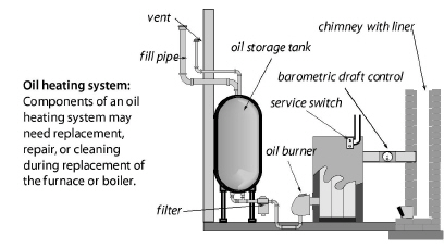
8.4.4 Oil-Fired Heating Installation
Oil-heating replacement should provide an oil-fired heating system in virtually new condition, even though components like the oil tank, chimney, piping, and wiring may remain in place.
Any maintenance, repair, or replacement for these remaining components should be part of the replacement job. Analyze design defects of the original system, and correct them during the heating-system replacement.
ü New oil-fired furnaces and boilers should have a minimum AFUE of 83%.
ü Install new oil-fired furnaces and boilers with adequate clearances to facilitate maintenance.
ü Inspect the existing chimney and the vent connector. Re-place the vent connector with Type L double-wall vent pipe if necessary.
ü Install a stainless steel chimney liner if necessary.
ü Verify that the clearances between the vent connector and nearby combustibles are adequate. See “Clearances to Combustibles for Vent Connectors” on page 310.
ü Install a new fuel filter, and purge the fuel lines as part of the new installation.
ü Consider dual-filtration on systems with nozzle sizes smaller than .65 gph.
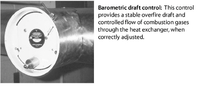
ü If required, install a new barometric damper in the vent if the old damper shows any sign of wear.
ü Verify that the presence of a functioning emergency shut-off for emergencies and service work. Inform clients of its function for emergencies only.
ü Look for a control that interrupts power to the burner in the event of a fire.
ü Measure the transformer voltage to verify that it complies with the manufacturer’s specifications.
ü Measure the control circuit amperage, and adjust the thermostat’s heat anticipator to match the amperage. Or, follow the thermostat manufacturer’s instructions for adjusting cycle length.
Testing New Oil-Fired Heating Systems
ü Verify that the oil pressure matches the manufacturer’s specifications, but isn’t less than 100 psi.
ü If the flue-gas temperature is too high, adjust oil pressure per manufacturers instructions or replace nozzle as necessary to produce the correct oil input (gpm) and flue-gas temperature.
ü Verify that the spray angle and spray pattern fit the size and shape of the combustion chamber.
ü As appropriate, adjust the barometric damper to achieve proper over-fire draft per manufacturer's instructions.
ü Adjust oxygen, flue-gas temperature, and smoke number to comply with manufacturer’s specifications. Smoke number should be zero on all modern oil-fired equipment.
Inspect the oil tank, and remove dirt and moisture at bottom of the tank. Verify that the oil tank and oil lines comply with NFPA 31.
Oil tanks are now almost always installed above ground. But many old oil tanks are still buried. Inspect above-ground tanks to find leaks.
Testing can evaluate both below-ground tanks and above-ground tanks for water in the fuel system.
1. Start by inspecting the oil filter for corrosion. Corrosion in the oil filter indicates a high probability of water and corrosion in the tank.
2. Next use water-finding paste, applied to the end of a probe, to detect water at the bottom of the oil tank. For indoor tanks, you’ll need a flexible probe because of the ceiling-height limitations.
See also NFPA 31 Chapter 7 Fuel Oil Tanks.
Inspecting Above-Ground Oil Tanks
Indoor oil leaks are usually accompanied by strong petroleum smells. Inspect the oil tank as well as all the oil piping between the oil tank and the oil-fired furnace.
ü Look for different colors on the tank from condensation, corrosion, or fuel leaks.
ü Look at the bottom of the oil tank and see if oil is dripping from a leak.
ü Look for patches from previous leaks.
ü If the oil tank is new, don’t mistake previous oil-tank leaks for leaks in the new tank.
ü Use the water test described previously.
If you smell oil but you can’t see the leak, consider the following tests.
ü Use the water test described previously.
ü For hidden leaks, consider ultrasound leak detection by a oil-tank specialist.
Advice for Below-Ground Oil Tanks
Leaky below-ground oil tanks are a financial problem and a major environmental problem. Local, state, or federal authorities may require homeowners to remove the tank, abandon it in place, or have it leak-tested by one of the following methods.
ü Use the water testing described previously.
ü A tank specialist collects multiple soil samples from around the tank and analyzes them for petroleum contamination by an approved method.
8.5 Combustion Space Heater Replacement
|
SWS Detail: 2.0201.2 Combustion Safety - Make-up Air, 2.0103.1 Combustion Worker Safety |
Space heaters are inherently more efficient than central heaters, because they have no ducts or distribution pipes.
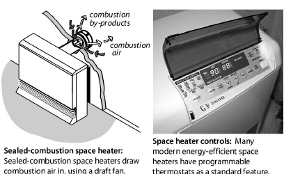
Weatherization agencies replace primary vented space heaters as an energy-conservation measure or for health and safety reasons. Choose a sealed-combustion space heater. Inspect existing space heaters for health and safety problems.
ü If power outages are common, select a space heater that operates without electricity.
ü Follow manufacturer’s venting instructions precisely.
ü Don’t vent sealed-combustion or induced-draft space heaters into naturally drafting chimneys.
ü Verify that flue-gas oxygen and temperature are within the ranges specified in Table 8-4 on page 275.
ü Install the equipment per manufacturer’s specifications.
Inform the client of the following operating instructions.
ü Don’t store any objects near the space heater that would restrict airflow around it.
ü Don’t use the space heater to dry clothes or for any purpose other than heating the home.
ü Don’t allow anyone to lean or sit on the space heater.
ü Don’t spray aerosols near the space heater. Many aerosols are flammable or can cause corrosion to the space heater’s heat exchanger.
|
SWS Detail: 2.0202.1 Unvented Space Heaters: Propane, Natural Gas, and Kerosene Heaters, 2.0401.1 Air Sealing Moisture Precautions |
Unvented space heaters include ventless gas fireplaces and gas logs installed in fireplaces previously designed for wood-burning or coal-burning. The unvented space heaters and fireplaces create indoor air pollution because they deliver all their combustion byproducts to the indoors.
Unvented space heaters aren’t safe. Replace them with vented space heaters or electric space heaters if at all possible.
DOE forbids unvented space heaters as primary heating units in weatherized homes. However, unvented space heaters may be used as secondary heaters, under these requirements and the requirements outlined in the Indiana Unvented Space Heater form.
1. The heater must conform to the safety standards of ANSI Z21.11.2.
2. The heater must have an input rating less than 40,000 BTUH.
3. The heater must be equipped with an oxygen-depletion sensing shut-off system.
4. The room containing the heater must have adequate combustion air.
5. CO production from unvented space heaters shall not exceed 200 PPM when measured on an air-free basis.
6. Home must have adequate ventilation: See “ASHRAE Standard 62.2–2016 Ventilation” on page 395.
8.6 Gas Burner Safety & Efficiency Service
Gas burners should be inspected and maintained during a service call. These following specifications apply to gas furnaces, boilers, water heaters, and space heaters.
8.6.1 Combustion Efficiency Test for Furnaces
Perform the following procedures at steady-state to verify a furnace’s acceptable operation.
Perform combustion testing with an electronic flue-gas analyzer that documents accurate combustion air temperature so that net stack temperature is calculated correctly. The testing location should be as close to the flue outlet of the unit as possible to reduce false O2 numbers and to obtain accurate flue gas temperatures.
• Measure temperature rise (supply minus return temperatures). Temperature rise should be within the manufacturer’s specifications for the furnace.
• Recommended flue-gas temperatures depend on the type of furnace and are listed in the table titled, “Combustion Standards for Gas Furnaces and Boilers” on page 275.
• As appropriate, adjust gas pressure so that temperature rise and flue-gas temperature meet manufacturer's specifications and per guidance from the National Fuel Gas Code (NFPA 54).
8.6.2 Inspecting Gas Combustion Equipment
At a minimum, inspect all gas-fired furnaces, boilers, water heaters, and space heaters according to these steps. For more complete information, follow the guidance in the appropriate Indiana Inspection form.
ü Look for soot, melted wire insulation, and rust in the burner and manifold inside and outside the burner compartment. These signs indicate flame roll-out, combustion gas spillage, CO, and incomplete combustion.
ü Inspect the burners for dust, debris, misalignment, flame-impingement, and other flame-interference problems. Clean, vacuum, and adjust as needed.
ü Inspect the heat exchanger for cracks, holes, or leaks.
ü Verify that furnaces and boilers have dedicated circuits with safety shutoffs nearby. Verify that all 120-volt wiring connections are enclosed in covered electrical boxes.
ü Verify that pilot is burning (if equipped) and that main burner ignition is satisfactory.
ü Check venting system for proper diameter and pitch. See page 307.
ü Check venting system for obstructions, blockages, or leaks.
ü Observe flame characteristics. Flames should be blue and well shaped. If flames are white or yellow, the burner may suffer from faulty combustion.
See “HVAC-System Commissioning” on page 250. See “Multi-Family HVAC-System Education” on page 251.
The goal of these measures is to minimize carbon monoxide (CO), stabilize flame, and verify the operation of safety controls.
ü Do an electronic combustion analysis and note the oxygen, CO, and flue-gas temperature.
ü Test for spillage and measure draft. Take action to improve the draft if it is inadequate because of improper venting, obstructed chimney, leaky chimney, or depressurization. See page 261.
ü If you measure CO and the measured oxygen level is low, open a window while observing CO level on the meter to see if CO is reduced by increasing the available combustion air through the open window. See “Worst-Case CAZ Depressurization Test” on page 256.
ü Adjust gas input if combustion testing indicates over-firing or under-firing.
ü For programmable thermostats, read the manufacturer’s instructions about how to control cycle length. These instructions may be printed inside the thermostat.
Burner Cleaning
Clean and adjust the burner if any of these conditions exists.
• CO is greater than 100 ppm as measured or 200 ppm air-free measurement for space heaters, water heaters, furnaces or boilers.
• You see indicators of soot or flame roll-out.
• Burners are visibly dirty.
• The appliance spills for more than two minutes or measured draft is inadequate. See page 307.
• The appliance hasn’t been serviced for two years or more.
Maintenance and Cleaning
Gas-burner and gas-venting maintenance should include the following measures.
ü Remove causes of CO and soot, such as over-firing, closed primary air intake, flame impingement, and lack of combustion air.
ü Remove dirt, rust, and other debris that may be interfering with the burners. Clean the heat exchanger if there are signs of soot around the burner compartment.
ü Seal leaks in vent connectors and chimneys.
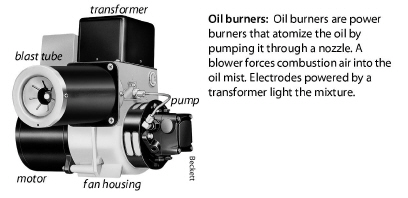
8.7 Oil Burner Safety and Efficiency Service
These procedures apply to oil-fired furnaces, boilers, and water heaters.
Oil burners require annual maintenance to maintain acceptable safety and combustion efficiency. Use combustion analysis to evaluate the oil burner and to guide maintenance and adjustment. Use other test equipment as discussed to measure other essential operating parameters and to make adjustments as necessary.
8.7.1 Oil Burner Testing and Adjustment
|
SWS Detail: 5.3003.2 Combustion Analysis of Oil-Fired Appliances |
Unless the oil-fired heating unit is very dirty or disabled, technicians should do combustion testing and adjust the burner for safe and efficient operation.
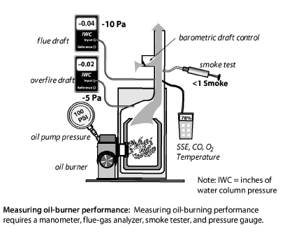
Combustion Testing and Adjustment
Combustion testing is essential to understanding the current oil burner performance and potential for improvement.
ü Sample the undiluted flue gases with a smoke tester, after reading the smoke tester instructions. Compare the smoke smudge left by the gases on the filter paper with the manufacturer’s smoke-spot scale to find the smoke number.
ü If the smoke number is higher than 3, take steps to reduce smoke before sampling the gases with a combustion analyzer to prevent the smoke from fouling the analyzer.
ü Sample undiluted flue gases between the barometric draft control and the appliance. Analyze the flue gas for O2, flue-gas temperature, CO, and steady-state efficiency (SSE).
ü Measure the draft over the fire inside the firebox (overfire draft) through a plug in the heating unit.
ü A flue gas temperature more than 450° F indicates that a clean heating unit is oversized. Exceptions: steam boilers and boilers with tankless coils. If the nozzle is oversized, replace the burner nozzle after selecting the correct nozzle size, spray angle, and spray pattern.
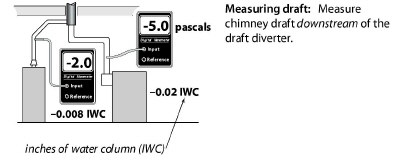
ü Adjust the barometric damper for a negative overfire draft of –0.020 IWC or –5 pascals at a test plug in the heating unit.
ü Adjust the air shutter to achieve the oxygen and smoke values, specified in Table 8-6 on page 298.
ü Adjust oxygen, flue-gas temperature, CO, and smoke number to match manufacturer’s specifications or specifications given here. Smoke number should be near zero on all modern oil-fired equipment.
Other Efficiency Testing and Adjustment
ü Adjust the gap between electrodes and their angle for proper alignment.
ü Measure the control-circuit amperage. Adjust the thermostat’s heat anticipator to match the amperage, or read the thermostat manufacturer’s instructions for adjusting cycle length.
ü Measure the oil-pump pressure, and adjust it to manufacturer’s specifications if necessary.
ü Measure the transformer voltage, and make sure it meets manufacturer's specifications.
ü Adjust the airflow or the water flow to reduce high flue-gas temperature if possible, but don’t reduce flue-gas temperature below 350°F.
8.7.2 Oil Burner Inspection and Maintenance
See “HVAC-System Commissioning” on page 250. See “Multi-Family HVAC-System Education” on page 251.
Use visual inspection and combustion testing to evaluate oil burner operation. An oil burner that passes visual inspection and complies with the specifications on page 298 may need no maintenance. Persistent unsatisfactory test results may indicate the need to replace the burner or the entire oil-fired heating unit.
Safety Inspection, Testing, and Adjustment
ü Inspect burner and appliance for signs of soot, overheating, fire hazards, corrosion, or wiring problems.
ü Inspect heat exchanger and combustion chamber for cracks, corrosion, or soot buildup.
ü If the unit smells excessively of oil, test for oil leaks and repair the leaks.
ü Time the flame sensor control or stack control to verify that the burner shuts off, within either 45 seconds or a time specified by the manufacturer, when the cad cell is blocked from seeing the flame.
ü Measure the high limit shut-off temperature and adjust or replace the high limit control if the shut-off temperature is more than 200° F for furnaces, or 220° F for hot-water boilers.
Oil Burner Maintenance
After evaluating the oil burner’s operation, specify some or all of these maintenance tasks as necessary, to optimize safety and efficiency.
ü Clean the burner’s blower wheel.
ü Clean dust, dirt, and grease from the burner assembly.
ü Replace oil filter(s) and nozzle.
ü Clean or replace air filter.
ü Remove soot from combustion chamber.
ü Remove soot from heat exchange surfaces.
ü Adjust gap between electrodes to manufacturer’s specs.
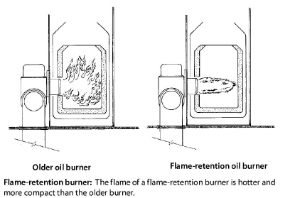
ü Check if the nozzle and the fire ring of the flame-retention burner is appropriate for the size of the combustion chamber.
ü Repair the ceramic combustion chamber, or replace it if necessary.
ü Verify correct flame sensor operation.
After these maintenance procedures, the technician carries out the diagnostic tests described previously to evaluate improvement made by the maintenance procedures and to determine whether more adjustment or maintenance is required.
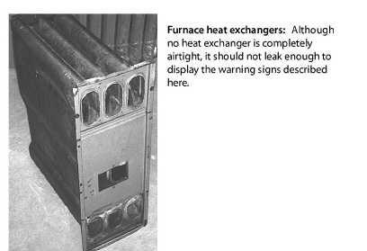
8.8 Inspecting Furnace Heat Exchangers
All furnace heat exchangers should be inspected as part of weatherization.
Leaks in heat exchangers are a common problem, causing the flue gases to mix with a building’s air. Ask occupants about respiratory problems, flu-like symptoms, and smells in the building when the heat is on. Also, check around supply registers for signs of soot, especially with oil heating. Consider using one or more of these six options for evaluating heat exchangers.
1. Look for rust at exhaust ports and vent connectors.
2. Look for flame-impingement on the heat exchanger during firing and flame-damaged areas near the burner flame.
3. Observe flame movement, change in chimney draft, or change in CO measurement when blower activates and deactivates.
4. Measure the flue-gas oxygen concentration before the blower starts and then again just after the blower starts. A change in oxygen level warrants further inspection. Note that this blower off/on test will not work for condensing furnaces. Oxygen levels for all types of furnaces should be steady once the appliance has reached Steady State.
5. Examine the heat exchanger by shining a bright light on one side and looking for light on the other side using a mirror to look into narrow locations.
6. Employ chemical detection techniques, according to the manufacturer’s instructions.
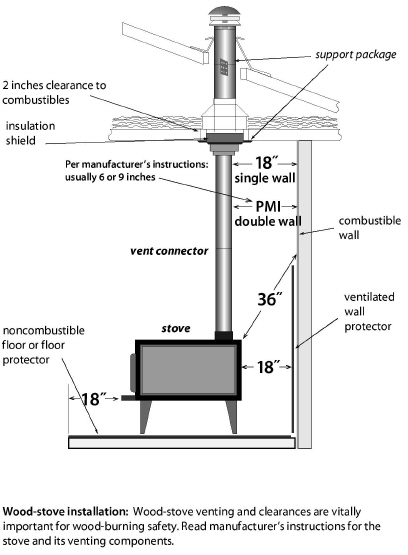
Step 1: Wood heating is a popular and effective auxiliary heating source for homes. However, wood stoves and fireplaces can cause indoor air pollution and fire hazards. Inspect wood stoves to evaluate potential hazards. Solid fuel appliances are to be inspected for venting and installation issues. Use the Indiana Wood Stove form to document information. See “DOE Health and Safety Guidance” on page 534.
Stoves that are listed by a testing agency like Underwriters Laboratory have installation instructions stating their clearance from combustibles. Unlisted stoves must adhere to clearances specified in NFPA 211.
Look for metal tags on the wood stove that list minimum clearances. Listed wood stoves may be installed to as little as 6 inches away from combustibles, if they incorporate heat shields and combustion design that directs heat away from the stove’s rear and side panels.
Unlisted stoves must be at least 36 inches away from combustibles. Ventilated or insulated wall protectors may decrease unlisted clearance from one-third to two thirds, according to NFPA 211. Always follow the stove manufacturer’s or heat-shield manufacturer’s installation instructions.
Floor Construction and Clearances
The floor of a listed wood stove must comply with the specifications on the listing (metal tag). Modern listed stoves usually sit on a 1-inch thick non-combustible floor protector that extends 18 inches beyond the stove in front.
The floor requirements for underneath an unlisted wood stove depends on the clearance between the stove and the floor, which depends on the length of its legs. Unlisted wood stoves must have floor protection underneath them unless they rest on a non-combustible floor. An example of a noncombustible floor is one composed of only masonry material.
An approved floor protector is either one or two courses of hollow masonry material (4 inches thick) with a non-combustible quarter-inch surface of steel or other non-combustible material on top of the masonry. This floor for a non-listed wood stove must extend no less than 18 inches beyond the stove in all directions.
Vent-Connector and Chimney Clearance
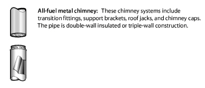
Interior masonry chimneys require a 2-inch clearance from combustibles and exterior masonry chimneys require a 1-inch clearance from combustibles. All-fuel metal chimneys (insulated double-wall or triple wall) usually require a 2-inch clearance from combustibles.
Double-wall stove-pipe vent connectors require a 9-inch clearance from combustibles or a clearance listed on the product. Single wall vent connectors must be at least 18 inches from combustibles. Wall protectors may reduce this clearance up to two-thirds.
See also “Wood-Stove Clearances” on page 303
All components of wood stove venting systems should be approved for use with wood stoves. Chimney sections penetrating floor, ceiling, or roof should have approved thimbles, support packages, and ventilated shields to protect nearby combustible materials from high temperatures.
Perform or specify the following inspection tasks.
ü Inspect stove, vent connector, and chimney for correct clearances from combustible materials as listed on stoves and vent assemblies or as specified in NFPA 211.
ü Each wood stove must have its own dedicated flue pipe. Two wood stoves may not share a single flue.
ü If the home is tight (<0.40 ACH), the wood stove should be equipped with a dedicated outdoor combustion-air duct.
ü Inspect vent connector and chimney for leaks. Leaks should be sealed with a high temperature sealant designed for sealing wood stove vents.
ü Galvanized-steel pipe must not be used to vent wood stoves.
ü Inspect chimney and vent connector for creosote build-up, and suggest chimney cleaning if creosote deposits exist.
ü Inspect the house for soot on seldom-cleaned horizontal surfaces. If soot is present, inspect the wood stove door gasket. Seal stove air leaks or chimney air leaks with stove cement. Improve draft by extending the chimney to reduce indoor smoke emissions.
ü Inspect stack damper and/or combustion air intake damper.
ü Check catalytic converter for repair or replacement if the wood stove has one.
ü Assure that heat exchange surfaces and flue passages within the wood stove are free of accumulations of soot or debris.
ü Wood stoves installed in manufactured homes must be approved for use in manufactured homes.
8.10 Inspecting Venting Systems
Combustion gases are vented through vertical chimneys or other types of approved horizontal or vertical vent piping. Identifying the type of existing venting material, verifying the correct size of vent piping, and making sure the venting conforms to the applicable codes are important tasks in inspecting and repairing venting systems. Too large a vent often leads to condensation and corrosion. Too small a vent can result in spillage. The wrong vent materials can corrode or deteriorate from heat.
The National Fire Protection Association (NFPA) publishes authoritative information on material-choice, sizing, and clearances for chimneys and vent connectors, as well as for combustion air. The information in this venting section is based on the following NFPA documents.
• NFPA 54: The National Fuel Gas Code
• NFPA 31: Standard for the Installation of Oil-Burning Equipment
• NFPA 211: Standard for Chimneys, Fireplaces, Vents, and Solid-Fuel-Burning Appliances
A vent connector connects the wood stove’s vent collar with the chimney. Approved vent connectors for gas-fired units are made from the following materials.
• Type-B vent, consisting of a galvanized steel outer pipe and aluminum inner pipe for gas-fired units.
• Type-L vent connector with a stainless-steel inner pipe and a galvanized-steel outer pipe for oil-fired units.
• Double-wall stove-pipe vent connector with a stainless-steel inner pipe and a black-steel outer pipe for solid-fuel units.
• Galvanized steel pipe for gas or oil-fired units only: See table.
|
Inches (gauge) |
|
|---|---|
|
5 and smaller |
0.022 (26 gauge) |
|
6 to 10 |
0.028 (24 gauge) |
|
11 to 16 |
0.034 (22 gauge) |
|
Larger than 16 |
0.064 (16 gauge) |
|
From International Mechanical Code 2009 |
|
Double-wall vent connectors are the best option, especially for appliances with some non-vertical vent piping. A double-wall vent connector maintains a sufficient flue gas temperature and prevents condensation.
Anywhere that draft is weak or flue gas temperature is low, use a double-wall vent connector. Gas appliances with draft hoods installed in attics or crawl spaces must use a Type-B vent connector. Use Type-L double-wall vent pipe for oil vent connectors in attics and crawl spaces.
Vent-Connector Requirements
Verify that vent connectors comply with these specifications.
• Vent connectors must be as large as the vent collar on the appliances they vent.
• Single wall vent-pipe sections must be fastened together with 3 screws or rivets at each joint.
• Vent connectors must be sealed tightly where they enter masonry chimneys.
• Vent connectors must be free of rust, corrosion, and holes.
• Maintain minimum clearances between vent connectors and combustibles.
• The chimney combining two draft-hood vent connectors must have a cross-sectional area equal to the area of the larger vent connector plus half the area of the smaller vent connector. This common vent must be no larger than 7 times the area of the smallest vent connector. For specific vent sizes, see the NFPA codes listed on page 308.
|
Vent diameter |
4" |
5" |
6" |
7" |
8" |
|
Vent area (square inches) |
12.6 |
19.6 |
28.3 |
38.5 |
50.2 |
• The horizontal length of vent connectors shouldn’t be more than 75% of the chimney’s vertical height or have more than 18 inches horizontal run per inch of vent diameter.
• Vent connectors must have upward slope to their connection with the chimney. NFPA 54 requires a slope of at least 1/4-inch of rise per foot of horizontal run so that combustion gases rise through the vent. The slope also prevents condensation from collecting in the vent and corroding it.
|
Diam (in) |
3" |
4" |
5" |
6" |
7" |
8" |
9" |
10" |
12" |
14" |
|
Length (ft) |
4.5' |
6' |
7.5' |
9' |
10.5' |
12' |
13.5' |
15' |
18' |
21' |
|
From International Fuel Gas Code 2000 |
||||||||||
• When two vent connectors connect to a single chimney, the vent connector servicing the smaller appliance must enter the chimney above the vent for the larger appliance.

There are two common types of vertical chimneys for venting combustion fuels that satisfy NFPA and ICC codes.
1. Masonry chimneys lined with fire-clay tile.
2. Manufactured metal chimneys, including all-fuel metal chimneys, Type-B vent chimneys for gas appliances, and Type L chimneys for oil appliances.
|
SWS Detail: 2.0203.2 Combustion Flue Gas—Orphaned Water Heaters |
Verify the following general specifications for building, inspecting, and repairing masonry chimneys.
• A masonry foundation should support every masonry chimney.
• Existing masonry chimneys should be lined with a fire clay flue liner. There should be a 1/2-inch to 1-inch air gap between the clay liner and the chimney’s masonry to insulate the liner. The liner shouldn’t bond structurally to the outer masonry because the liner needs to expand and contract independently of the chimney’s masonry structure. The clay liner seal to the chimney cap with a flexible high-temperature sealant.
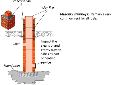
• Masonry chimneys should have a cleanout 12 inches or more below the lowest inlet. Clean mortar and brick dust out of the bottom of the chimney through the clean-out door, so that this debris won’t eventually interfere with venting.
• Seal the chimney’s penetrations through floors and ceilings with sheet metal and non-combustible sealant as a fire-stop and air barrier.
• Re-build deteriorated or unlined masonry chimneys as specified here or reline them as part of a heating-system replacement or a venting-safety upgrade. Or, install a new metal chimney instead of repairing the existing masonry chimney.
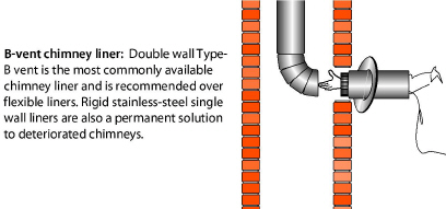
Metal Liners for Masonry Chimneys
Install or replace liners in unlined masonry chimneys or chimneys with deteriorated liners as part of heating system replacement. Orphaned water heaters may also need a chimney liner because the existing chimney may be too large after the retrofit. Use a correctly sized Type-B vent, a flexible or rigid stainless-steel liner, or a flexible aluminum liner.
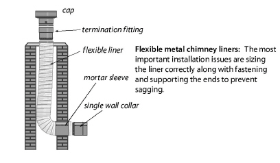
Flexible liners require careful installation to avoid a low spot at the bottom, where the liner turns a right angle to pass through the wall of the chimney. Comply with the manufacturer’s instructions, which usually require stretching the liner and fastening it securely at both ends, to prevent the liner from sagging and creating a low spot.
Flexible liners are easily damaged by falling masonry debris inside a deteriorating chimney. Use B-vent, L-vent, or single-wall stainless steel pipe instead of a flexible liner when the chimney is significantly deteriorated.
To minimize condensation, insulate the flexible liner — especially when installed in exterior chimneys. Consider fiberglass-insulation jackets or perlite, if the manufacturer’s instructions allow. Wood-stove chimney liners must be stainless steel and insulated.
Sizing flexible chimney liners correctly is very important. Oversizing is common and can lead to condensation and corrosion. The manufacturers of the liners include vent-sizing tables in their specifications. Liners should display a label from a testing lab like Underwriters Laboratories (UL).
Masonry chimneys as structural hazards: A building owner may want to consider reinforcing a deteriorated chimney by re-pointing masonry joints or parging the surface with reinforced plaster. Other options include demolishing the chimney or filling it with concrete to prevent it from damaging the building by collapsing during an earthquake.
Solutions for Failed Chimneys
Sometimes a chimney is too deteriorated to be re-lined or repaired. In this case, abandon the old chimney, and install one of the following.
• A double-wall horizontal sidewall vent, equipped with a barometric draft control and a power venter mounted on the exterior wall. Maintain a 4-foot clearance between the ground and the vent’s termination if you live where it snows.
• A new heating unit, equipped with a power burner or draft inducer, that is designed for horizontal or vertical venting.
• A new manufactured metal venting system.
• A new sealed-combustion heating unit, equipped with a combustion-air source from outdoors.
Manufactured metal chimneys have engineered parts that fit together in a prescribed way. Parts include: metal pipe, weight-supporting hardware, insulation shields, roof jacks, and chimney caps. One manufacturer’s chimney may not be compatible with another’s connecting fittings.
All-fuel chimneys (also called Class A chimneys) are used primarily for the solid fuels: wood and coal. All-fuel metal chimneys come in two types: insulated double-wall metal pipe and triple-wall metal pipe. Comply with the manufacturer’s specifications when you install these chimneys.
Type-B vent double-wall pipe is permitted as a chimney for gas appliances. Type BW pipe is manufactured for gas space heaters in an oval shape to fit inside wall cavities.
Type L double-wall pipe is used for oil chimneys.
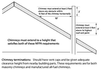
Masonry chimneys and all-fuel metal chimneys should terminate at least three feet above the roof penetration and two feet above any obstacle within ten feet of the chimney outlet.
Type B vents can terminate as close as one foot above flat roofs and above pitched roofs up to a 6/12 roof pitch. As the pitch rises, the minimum required termination height as measured from the high part of the roof slope, rises as shown in this table.
|
flat- 6/12 |
6/12- 7/12 |
7/12- 8/12 |
8/12- 9/12 |
9/12- 10/12 |
10/12- 11/12 |
11/12- 12/12 |
12/12- 14/12 |
14/12- 16/12 |
16/12- 18/12 |
|
1' |
1' 3" |
1' 6" |
2' |
2' 6" |
3' 3" |
4' |
5’ |
6' |
7' |
|
From National Fuel Gas Code 2009 |
|||||||||
8.11.4 Air Leakage through Masonry Chimneys
|
SWS Detail: 4.1001.3 Fireplace Chimney and Combustion Flue Vents |
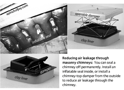
The existing fireplace damper or “airtight” doors seldom provide a good air seal. Help the client decide whether to use the fireplace in the future or whether to take it out of service. Consider these solutions for chimneys with ineffective or missing dampers.
• Install an inflatable chimney seal along with a notice of its installation to alert anyone wanting to start a fire to remove the seal first.
• Install an operable chimney-top damper and leave instructions on how to open and close it. Also communicate to users of which position is open and which is closed.
• Air seal the chimney top from the roof with a watertight, airtight seal. Also seal the chimney from the living space with foam board and drywall. If you install a permanent chimney seal such as this, post a notice at the fireplace saying that it is permanently disabled.
8.12 Special Venting Considerations for Gas
The American Gas Association (AGA) publishes a classification system for venting systems attached to natural-gas and propane appliances. This classification system assigns Roman numerals to four categories of venting based on whether there is positive or negative pressure in the vent and whether condensation is likely in the vent.
.
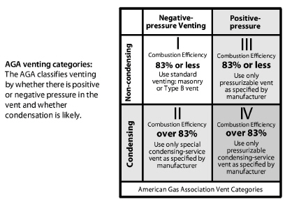
A majority of gas appliances found in homes and multifamily buildings are Category I. They have negative pressure in their vertical chimneys. We expect no condensation in the vent connector or chimney in a Category I appliance.
Condensing furnaces are usually Category IV, have positive pressure in their vent, and condensation occurring in both the appliance and vent.
Category III vents are rare, however a few fan-assisted furnaces and boilers vent their flue gases through airtight non-condensing vents. Category II vents are very rare and beyond the scope of this discussion.
8.12.1 Venting Fan-Assisted Furnaces and Boilers
Newer gas-fired fan-assisted central furnaces and boilers eliminate dilution air and may have slightly cooler flue gases compared to their predecessors. The chimney may experience more condensation than in the past. Inspect the existing chimney to verify that it’s in good condition when considering replacing an old natural-draft unit. Reline the chimney when you see any of these conditions.
• When the existing masonry chimney is unlined.
• When the old clay or metal chimney liner is deteriorated.
• When the chimney is too large for the smallest Btuh appliance. Refer to NFPA 54 vent sizing guidance.
• When an 80% mid-efficiency furnace is vented into a masonry chimney by itself, regardless of the condition of the chimney.
Liner Materials for 80+ Furnaces
For gas-fired 80+ AFUE furnaces, a chimney liner should consist of one of these four materials.
1. A type-B vent
2. A rigid or flexible stainless steel liner (preferably insulated)
3. A poured masonry liner
4. An insulated flexible aluminum liner
Chimney relining is expensive. Therefore consider instead a power-vented sealed-combustion unit when an existing chimney is inadequate for a new fan-assisted appliance.
8.12.2 Venting Sealed-Combustion Furnaces and Boilers
Some space heaters, furnaces, and boilers use seamless, stainless steel vents for Category III venting (e.g. - AL29-4C) that vent horizontally under positive pressure.
Condensing furnaces usually employ horizontal or vertical plastic-pipe chimneys.
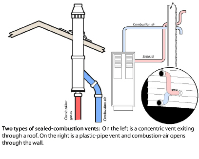
Stainless-steel vents powered by fans in gas and oil appliances exit through walls and don’t require vertical chimneys.
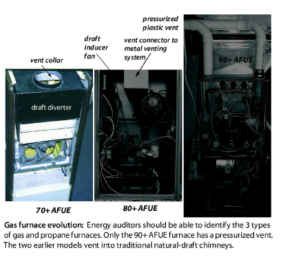
|
Annual Fuel Utilization Efficiency (AFUE) |
Operating characteristics |
|---|---|
|
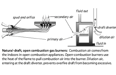
70+ |
Category I, draft diverter, no draft fan, standing pilot, non-condensing, indoor combustion and dilution air. |
|
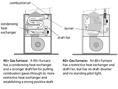
80+ |
Category I, no draft diverter, fan-assisted draft, electronic ignition, indoor combustion air, no dilution air. |
|
80+ |
Category III, horizontal fan-pressurized non-condensing airtight vent, indoor combustion air, no dilution air. |
|
90+ |
Category IV, no draft diverter, fan-assisted draft, low-temperature plastic venting, positive draft, electronic ignition, condensing heat exchanger, outdoor combustion air is strongly recommended. |
|
SWS Detail: 5.3003.4 Evaluating Electrical Service, 5.3003.11 Heating and Cooling Controls, 5.3003.26 Electrical Service—Mid and High Rise, 5.3003.4 Evaluating Electrical Service |
The forced-air system consists of an air handler (furnace, heat pump, air conditioner) with its heat exchanger along with attached ducts. The annual system efficiency of forced-air heating and air-conditioning systems depends on the following issues.
• Duct leakage
• System airflow
• Blower operation
• Balance between supply and return air
• Duct insulation levels
The evaluation and improvement of ducts has a logical sequence of steps.
1. Solve the airflow problems because a contractor might have to replace ducts or install additional ducts.
2. Determine whether the ducts are located inside the thermal boundary or outside it.
3. Evaluate the ducts’ air leakage and decide whether duct-sealing is important and if so, find and seal the duct leaks.
4. If supply ducts are outside the thermal boundary or if condensation is an air-conditioning problem, insulate the ducts.
8.13.2 Solving Airflow Problems
You don’t need test instruments to discover dirty blowers or disconnected branch ducts. Find these problems before measuring duct airflow, troubleshooting the ducts, or sealing the ducts. These steps precede airflow measurements.
1. Ask the client about comfort problems and temperature differences in different rooms of the home.
2. Based on the clients comments, look for disconnected ducts, restricted ducts, and other obvious problems.
3. Inspect the filter(s), blower, and indoor coil for dirt. Clean them if necessary. If the indoor coil isn’t easily visible, a dirty blower means that the coil is probably also dirty.
4. Look for dirty or damaged supply and return grilles that restrict airflow. Clean and repair them.
5. Look for closed registers or closed balancing dampers that could be restricting airflow to uncomfortable rooms.
6. Notice kinked, or un-stretched flex duct and repair the flex duct as necessary.
7. Notice moisture problems like mold and mildew. Moisture sources, like a wet crawl space, can overpower air conditioners by introducing more moisture into the air than the air conditioner can remove.
Measuring Total External Static Pressure (TESP)
The blower creates the duct pressure that you can measure in inches of water column (IWC) or pascals. The return static pressure is negative and the supply static pressure is positive. Total external static pressure (TESP) is the sum of the absolute values of the supply and return static pressures. Absolute value means that you ignore the positive or negative signs when adding supply static pressure and return static pressure to get TESP. This addition represents the distance on a number line as shown in the illustration here.
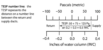
TESP gives a rough indicator of whether airflow is adequate or not. The greater the TESP, the less the airflow. The supply and return static pressures by themselves can indicate whether the supply or the return or both sides are restricted. For example, if the supply static pressure is 0.10 IWC (25 pascals) and the return static pressure is –0.5 IWC (-125 pascals), you can assume that most of the airflow problems are due to a restricted or undersized return.
The TESP gives a rough estimate of airflow if the manufacturer’s graph or table for static pressure versus airflow is available.
1. Attach two static pressure probes to tubes leading to the two ports of the manometer. Attach the high-side port to the probe inserted downstream of the air handler in the supply duct. The other tube goes upstream of the air handler in the return duct. The manometer adds the supply and return static pressures to measure TESP.
2. Consult manufacturer’s literature for a table of TESP versus airflow for the blower or the air handler. Find airflow for the TESP measured in Step 1.
3. Measure pressure on each side of the air handler to obtain both supply and return static pressures separately. This test helps to locate the main problems as related to either the supply or the return.
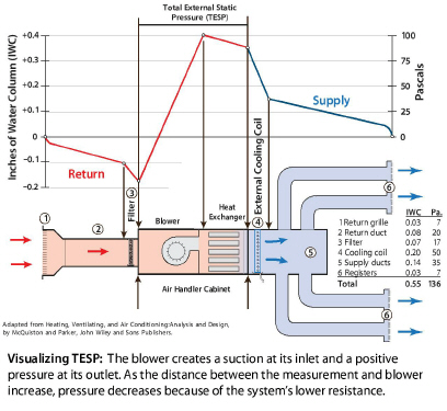
Static Pressure Guidelines
Air handlers deliver their airflow at TESPs ranging from 0.30 IWC (75 Pascals) to 1.0 IWC (250 Pascals) as found in the small buildings. Manufacturers maximum recommended static pressure is usually 0.50 IWC (125 pascals) for standard air handlers. TESPs greater than 0.50 IWC indicate inadequate airflow in standard residential forced-air systems.
The popularity of pleated filters, electrostatic filters, and high-static high-efficiency evaporator coils, prompted manufacturers to introduce premium air handlers that can deliver adequate airflow at a TESP of greater than 0.50 IWC (125 pascals).
Premium residential air handlers can provide adequate airflow with TESPs of up to 0.90 IWC (225 pascals) because of their more powerful blowers and variable-speed blowers. TESPs greater than 0.90 IWC indicate the possibility of inadequate airflow in these premium residential air handlers.
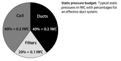
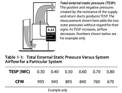
8.13.3 Unbalanced Supply-Return Airflow Test
Closing interior doors often separates supply registers from return registers in homes with central returns. A bedroom without a return register and with a closed door restricts the bedroom air from returning to the air handler. This restriction pressurizes bedrooms and depressurizes the central areas near return registers. These pressures can drive air leakage through the building shell, create moisture problems, and bring pollutants in from the crawl space, garage, or CAZ.
The following tests use only the air handler and a digital manometer to evaluate whether the supply air can flow back to the return registers relatively unobstructed. Activate the air handler and close interior doors.
1. Measure the pressure difference between the home’s central living area and the outdoors with a digital manometer.
2. Measure the bedrooms’ pressure difference with reference to outdoors.
3. Or, you can measure the pressure difference between the central zone and the bedroom.
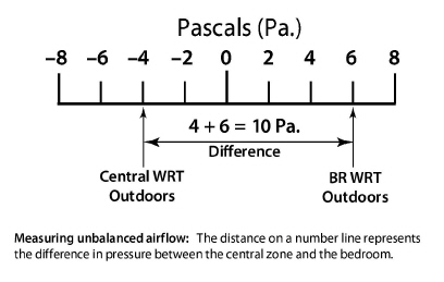
If the difference between the bedroom and central zone is more than 3.0 pascals with the air handler operating, pressure relief is desirable. Like TESP, disregard the positive or negative signs, and add the absolute values.
There will be times, particularly in tighter dwellings, that door closure will cause a pressure imbalance in the main body even if the rooms are 3.0 pascals or less. Because this can cause a variety of problems, consider the following:
• Any time the central area of the home changes pressure with reference to outside due to interior door closure, consider pressure relief regardless of the pressure change. Evaluate the pressure change n light of CAZ pressure diagnostics and other potential issues such as building durability, comfort and efficiency.
• Measure and record the main body pressure when you perform room pressure measurements.
To estimate the amount of pressure relief needed, slowly open the bedroom door until the pressure difference drops below 1 pascal.
Estimate the surface area of that door opening. This is the area of the permanent opening required to provide pressure relief. Pressure relief may include undercutting the door, installing transfer grilles or installing jumper ducts. Another, more expensive, option would be to install a dedicated return duct directly to the problem room.
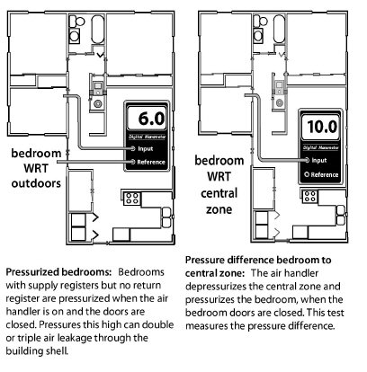
8.13.4 Evaluating Furnace Performance
|
SWS Detail: 5.3003.4 Evaluating Electrical Service, 5.3003.26 Electrical Service—Mid and High Rise |
The effectiveness of a furnace depends on its temperature rise, fan-control temperatures, and flue-gas temperature. For efficiency, you want a low temperature rise. However, the furnace must maintain a minimum flue-gas temperature to prevent corrosion in the venting of 70+ and 80+ AFUE units.
Apply the following furnace-operation standards to maximize the heating system’s seasonal efficiency and safety.
ü Perform a combustion analysis as described in “Gas Burner Safety & Efficiency Service” on page 292.
ü Check temperature rise after 5 minutes of operation. Refer to manufacturer’s nameplate for acceptable temperature rise (supply temperature minus return temperature). The temperature rise should be between the minimum and maximum temperature rise on the nameplate. Prefer the lower end of this range for energy efficiency.
ü With temperature-activated controls, verify that the fan-on temperature is 120–140° F. The lower the better.
ü With time-activated fan controls, verify that the fan is switched on with the shortest time delay available if it’s adjustable. The control should switch the fan off when the fan off temperature is 20° to 30° above the measured return-air temperature.
ü Verify that the high-limit controller shuts the burner off before the furnace temperature reaches manufacturer’s maximum outlet temperature.
ü Verify that there is a strong noticeable airflow from all supply registers.
ü Adjust fan control to conform to the operating parameters on the diagram or replace the fan control if this adjustment fails. Some fan controls aren’t adjustable.
ü Adjust the high limit control to conform to the operating parameters on the diagram, or replace the high-limit control.
ü All forced-air heating systems must deliver supply air and collect return air only from inside the conditioned rooms of the house. Taking return air from an un-heated area of the house such as an unconditioned basement or a crawl space isn’t acceptable.
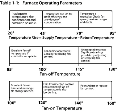
8.13.5 Rooftop Units (Air Handlers)
|
SWS Detail: 5.3003.4 Evaluating Electrical Service, 5.3003.26 Electrical Service—Mid and High Rise, 5.3003.11 Heating and Cooling Controls |
Rooftop units (RTUs) are air handlers located on roofs or on slabs or platforms outdoors. RTUs may contain one or more of the following.
• A combustion furnace
• All the components of an air conditioner (packaged or unitary air conditioner)
• All the components of an heat pump (packaged or unitary heat pump)
• Outdoor-air damper with another damper, called an economizer for ventilation and free cooling.
A controller in the economizer measures the temperature (and humidity in humid climates) of the outdoor air. When the outdoor conditions are favorable, the control switches the air conditioning compressor off and cools the building with outdoor air instead. The economizer uses far less cooling energy compared to air conditioning.
Economizers typically operate at night when the outdoor air is cooler than the indoor air in a process known as “free cooling”. Economizers mix enough outdoor air into the indoor air in order to meet the thermostat setpoint (which may be lower than the AC setpoint), without using the compressor.
Fresh air that economizers exchange with indoor air while they save cooling energy at night can also count as ventilation. Therefore the ventilation system can run for fewer hours and avoid operating during the day’s peak electrical load.
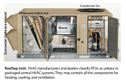
RTU Maintenance and Improvement
Because RTUs are located outdoors, they are even more likely to be neglected compared to indoor air handlers. Fortunately though, the RTU’s components are more accessible compared to indoor air handlers.
Consider the following maintenance and improvements for RTUs.
ü Clean or change filters, provide extra filters, and educate the building owner on filter maintenance.
ü Test the combustion furnace as you would an indoor furnace.See “Combustion-Safety Evaluation” on page 251.
ü Clean the evaporator and condenser coils as specified on page 378.
ü Test the RTU and its ducts for air leakage because many RTUs systems have high duct leakage. See “Air Filter Effectiveness” on page 339.
ü Test and adjust the economizer to maximize its benefit for both free cooling and ventilation. This requires an elite HVAC controls technician.
ü Educate the building owner or operator on economizer function and control. Replace the thermostat, if necessary to accommodate optimal economizer functioning. Note: Economizers functioning isn’t intuitive and therefore many, if not most, economizers function poorly.
8.13.6 Recommended Airflow for Air Handlers
The air handler’s recommended airflow depends on its heating or cooling capacity. For combustion furnaces, provide 11-to-15 CFM of airflow for each 1000 BTUH of output. Verify minimum cross-sectional area of ducts for both the supply and return sides of the duct system per the following estimation:
• Draft hood units: 2 sq.in. per each 1000 BTUH input
• Mid efficiency (80+): 2.5 sq.in. per each 1000 BTUH input
• High efficiency (90+): 3 sq.in. per 1000 BTUH input
Remember that air flow is limited by the smallest sections and the equivalent footage of the duct system. Also, a properly sized plenum may be irrelevant if there are insufficient runs coming off of it.
Central air conditioners and heat pumps should deliver 400 CFM +/- 10% of airflow per ton of cooling capacity (one ton equals 12,000 BTUH). This airflow standard typically requires a duct system with at least 6 square inches of cross-sectional area of both supply plenum and return plenum for each 1000 BTUH of air-conditioning or heat-pump capacity.
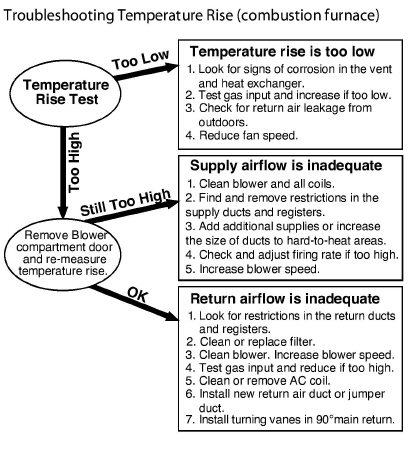
8.13.7 Improving Forced-Air System Airflow
Inadequate airflow is a common cause of comfort complaints. When the air handler is on there should be a strong airflow out of each supply register. Low register airflow may mean that a branch duct is blocked or separated, or that return air from the room to the air handler isn’t sufficient.
When low airflow is a problem, consider specifying the following improvements as appropriate from your inspection.
ü Clean or change filter. Select a less restrictive filter (lower MERV rating) if you need to reduce static pressure substantially.
ü Clean air handler’s blower.
ü Clean the air-conditioning coil or heat pump coil. If the blower is dirty, the coil is probably also dirty.
ü On a condensing furnace, clean the secondary heat exchanger coil.
ü Increase blower speed.
ü Make sure that balancing dampers to rooms that need more airflow are wide open.
ü Lubricate the blower motor, and check tension on drive belt.
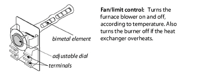
Duct Improvements to Increase Airflow
Consider specifying the following duct changes to increase system airflow and reduce the imbalance between supply airflow and return airflow.
ü Modify the filter installation to allow easier filter changing, if filter changing is currently difficult.
ü Remove obstructions to registers and ducts such as rugs, furniture, and objects placed inside ducts (children’s toys and water pans for humidification, for example).
ü Remove kinks from flex duct, and replace collapsed flex duct and deteriorating fiberglass duct board.
ü Remove excessive lengths of slacking flex duct, and stretch the duct to enhance airflow.
ü Perform a Manual D sizing procedure to evaluate whether to replace branch ducts that are too small.
ü Install additional supply ducts, return ducts, and registers as needed to provide heated air throughout the building, especially in additions to the building.
ü Undercut bedroom doors, especially in homes without return registers in bedrooms.
ü Repair or replace bent, damaged, or restricted registers. Install low-resistance registers and grilles.
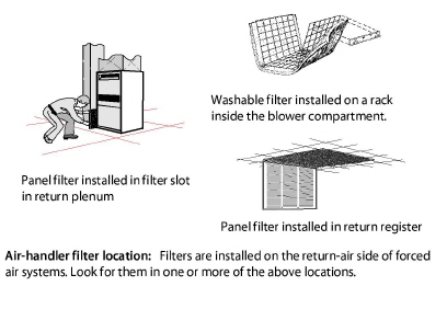
8.13.8 Air Filtration for Air Handlers
Manufacturers equip air handlers with air filters at the factory or recommend that installers install air filters in return ductwork. The purpose of these filters is to protect the blower and heat exchangers from fouling by dust.
Another possible function for air filters is to remove particles from indoor air. This function is useful when the outdoor environment contains a lot of particles, such in large cities, rural areas where wind and agriculture create particulates, or during forest fires.
The most common filter-rating method is the Minimum Efficiency Rating Value (MERV). A higher MERV rating means that the filter removes more particles and a larger fraction of smaller particles.
The MERV rating system divides particles into three size categories: 0.3–1, 1–3, and 3–10 microns. The two smallest categories are the most important for human health, as small respirable particles (PM2.5) can more easily deposit in the lungs compared to larger particles.
The need for high MERV filters depends on the severity of the particle problem in a building. Particles less than 2.5 microns are the most dangerous because they can lodge themselves deep in the lungs. Filtering air with a long-running central air handler or a portable air cleaner can be energy intensive and it may or may not be effective.
The MERV ratings of available HVAC filters range from MERV 3 to MERV 16, with higher ratings removing more particles at smaller sizes. A MERV 3 filter captures large particles — clothing fibers, pollen, and dust mites, but few smaller respirable particles. A MERV16 filter captures more than 95% of all three particle sizes, including bacteria and tobacco smoke. The minimum MERV rating to remove 50% of the respirable 1–3 microns particle-size range is MERV 10. See also "Air Filtration for Indoor Air Quality" on page 416.
Air Filter Pressure and Airflow Effects
Air filters affect the airflow and energy consumption of forced air HVAC systems and balanced ventilation systems. Before choosing the type of air filter, consider its MERV rating and a home’s need for particle removal.
HVAC designers designed air handlers for use with low-MERV filters with a small pressure drop. Changing to higher-MERV filters can cause the filter pressure drop to increase and the system airflow to decrease.
Insufficient airflow may cause blowers to fail prematurely as they struggle to overcome system pressures beyond their design specification. For heating systems, the furnaces may overheat and cycle on their high limit switches. Airflow reductions in cooling systems risk coil icing and premature compressor failure. See also "Air Filtration for Indoor Air Quality" on page 416.
To reduce the resistance of an high-MERV air filter, consider installing steps to accommodate a larger filter with more surface area and less static-pressure drop compared to the existing filter.
• A slanted filter bracket assembly
• An enlarged filter fitting to allow a filter with more surface area
• Filters in each return register instead of only one at the air handler.
8.14 Evaluating Duct Air Leakage
Duct leakage is a major energy-waster in buildings where the ducts reside outside the home’s thermal boundary in a crawl space, attic, attached garage, or unconditioned basement. When these intermediate zones remain outside the thermal boundary after weatherization, duct sealing is usually cost-effective.
Duct leakage inside the thermal boundary isn't usually a severe energy or comfort problem unless the leaks are causing pressure imbalances in the dwelling or duct zone.
8.14.1 Troubleshooting Duct Leakage
Locate the duct leaks and evaluate their severity using one or more of the following procedures.
Finding Duct Leaks Using Touch and Sight
One of the simplest ways of finding duct leaks is feeling with your hand for air leaking out of supply ducts, while the ducts are pressurized by the air handler’s blower. Duct leaks can also be located using light.
Use one of these 4 tests to locate air leaks.
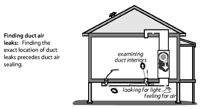
1. Use the air handler blower to pressurize supply ducts. Closing the dampers on supply registers temporarily or partially blocking the register with pieces of carpet, magazines, or any object that won’t be blown off by the register’s airflow increases the duct pressure and make duct leaks easier to find. Dampening your hand makes your hand more sensitive to airflow, helping you to find duct air leaks.
2. Place a trouble light, with a 100-watt bulb, inside the duct through a register. Look for light emanating from the exterior of duct joints and seams.
3. Determine which duct joints were difficult to fasten and seal during installation. These joints are likely duct-leakage locations.
4. Use a trouble light, flashlight, and mirror or a digital camera to help you to visually examine duct interiors.
Feeling air leaks establishes their exact location. Ducts must be pressurized in order to feel leaks. You can feel air leaking out of pressurized ducts, but you can’t feel air leaking into depressurized return ducts. Pressurizing the home with a blower door forces air through duct leaks, located in intermediate zones, where you can feel the leakage coming out of both supply and return ducts.
Pressure pan tests can identify leaky or disconnected ducts located in intermediate zones. Pressure pan measurements are taken at supply and return registers while using the blower door to depressurize the house to -50 pascals.
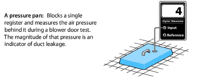
If the ducts are located within the thermal boundary, typically, pressure pan testing isn't really necessary if the following steps are taken.
• Returns are sealed in the CAZ, basements or crawlspaces for H&S reasons.
• Verify that the duct zone pressure does not change when the air handler is operated.
Pressure pan testing is required when ducts are located outside the thermal boundary or when returns are part of the building structure such as panned floor joists or wall cavities. For comprehensive pressure pan testing, use the following guidance.
1. Install blower door and set-up house for winter conditions. Open all interior doors.
2. If the basement is conditioned living space, open the door between the basement and upstairs living spaces.
3. If the basement isn’t conditioned living space, close the door between basement and upstairs. Then measure and record the zone pressure of the basement with reference to the conditioned space to confirm that the conditioned space and basement are separate spaces with a substantial pressure difference between them.
4. Turn furnace off at the thermostat or main switch. Remove furnace filter, and temporarily tape filter slot if one exists. Be sure that all grilles, registers, and dampers are fully open.
5. Temporarily seal any outside fresh-air intakes to the duct system.
6. Seal supply registers in unoccupied zones that aren’t intended to be heated — an unconditioned basement or crawl space, for example.
7. Open attics, crawl spaces, and garages as much as possible to the outdoors so they don’t create a secondary air barrier.
8. Connect hose between pressure pan and the input tap on the digital manometer. Leave the reference tap open.
9. With the blower door’s manometer reading –50 pascals, place the pressure pan completely over each grille or register one by one to form a tight seal. Leave all other grilles and registers open when making a test. Record each reading, which should give a positive pressure.
10. If a grille is too large or a supply register is difficult to cover with the pressure pan (under a kitchen cabinet, for example), seal the grille or register with masking tape. Insert a pressure probe through the masking tape and record the reading. Remove the tape after the test.
11. Use either the pressure pan or tape to test each register and grille in a systematic way.
If the ducts are perfectly sealed with no leakage to the outdoors, you won’t measure any pressure difference (0.0 pascals) during a pressure-pan test. The higher the measured pressure reading, the more connected the duct is to the outdoors.
• For H&S reasons, seal all returns located in the CAZ, basement or crawlspace.
• Seal any ducts located inside the thermal boundary that are causing a pressure imbalance.
• To the best of your ability, ducts located outside the thermal boundary should be sealed to a pressure pan reading of 1 pa or less.
• The reduction you achieve depends on your ability to find the leaks and whether you can access the leaky ducts. The best weatherization agencies use 1 pascal or less as a general goal for all registers.
• After duct sealing, make sure airflow is still adequate for heating and cooling systems. Recheck temperature rise on heating systems and airflow for heat pumps and air conditioners.
Supply and return terminations found outside the conditioned space are to be removed and the ducts sealed. Removal of unnecessary ducts in unconditioned spaces is recommended.
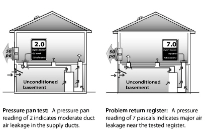
8.14.2 Measuring Duct Air Leakage with a Duct Blower
The duct blower is the most accurate common measuring device for duct air leakage. It consists of a fan, a digital manometer or set of analog manometers, and a set of reducer plates for measuring different leakage levels.
Pressurizing the ducts with a duct blower measures total duct leakage. Using a blower door with a duct blower measures leakage to outdoors.
Measuring Total Duct Leakage
The total duct leakage test measures leakage to both indoors and outdoors. The house and intermediate zones should be open to the outdoors by way of windows, doors, or vents. Opening the intermediate zones to outdoors insures that the duct blower is measuring only the ducts’ airtightness — not the airtightness of ducts combined with other air barriers like roofs, foundation walls, or garages.
Supply and return ducts can be tested separately, either before the air handler is installed in a new home or when an air handler is removed during replacement.
Follow these steps when performing a duct airtightness test.
1. Install the duct blower in the air handler or to a large return register, either using its connector duct or simply attaching the duct blower itself to the air handler or return register with cardboard and tape.
2. Remove the air filter(s) from the duct system.
3. Seal all supply and return registers with masking tape or other non-destructive sealant.
4. Open the house, basement or crawl space, containing ducts, to outdoors.
5. Drill a 1/4 or 5/16-inch hole into a supply duct a short distance away from the air handler and insert a manometer hose. Connect a manometer to this hose to measure duct with reference to (WRT) outdoors. (Indoors, outdoors, and intermediate zones should ideally be opened to each other in this test).
6. Connect an airflow manometer to measure fan WRT the area near the fan.
Check manometer(s) for proper settings. Digital manometers require your choosing the correct mode, range, and fan-type settings.
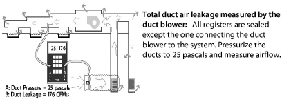
1. Turn on the duct blower and pressurize the ducts to 25 pascals.
2. Record duct-blower airflow.
3. While the ducts are pressurized, start at the air handler and move outward feeling for leaks in the air handler, main ducts, and branches.
4. After testing and associated air-sealing are complete, restore filter(s), remove seals from registers, and check air handler.
Measuring Duct Leakage to Outdoors
Measuring duct leakage to outdoors gives you a duct-air-leakage value that is directly related to energy waste and the potential for energy savings.
1. Set up the home in its typical heating and cooling mode with windows and outside doors closed. Open all indoor conditioned areas to one another.
2. Install a blower door, configured to pressurize the home.
3. Connect the duct blower to the air handler or to a main return duct.
4. Pressurize the ducts to +25 pascals by increasing the duct blower’s speed until this value is reached.
5. Pressurize the house until the pressure difference between the house and ducts is 0 pascals (house WRT ducts). See "Blower-Door Test Procedures" on page 506.
6. Read the airflow through the duct blower. This value is duct leakage to outdoors.

8.14.3 Measuring House Pressure Caused by Duct Leakage
The following test measures pressure differences between the house and outdoors, caused by duct leakage. Try to correct pressure differences because of the air leakage through the building enclosure that the pressure differences create.
1. Close all windows and exterior doors. Turn-off all exhaust fans.
2. Open all interior doors, including door to basement.
3. Measure the baseline house-to-outdoors pressure difference and zero it out using the baseline procedures described in “Blower-Door Test Procedures” on page 506.
4. Turn on air handler.
5. Measure the house-to-outdoors pressure difference. This test indicates dominant duct leakage as shown here.
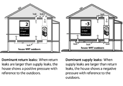
A positive pressure indicates that the return ducts (which pull air from leaky intermediate zones) are leakier than the supply ducts. A negative pressure indicates that the supply ducts (which push air into intermediate zones through their leaks) are leakier than return ducts. A pressure at or near zero indicates equal supply and return leakage or else very little duct leakage.
Seal ducts located outside the thermal boundary or in an intermediate zone like a ventilated attic or crawl space. Leaks nearer to the air handler are exposed to higher pressure and are more important than leaks farther away.
8.15.1 General Duct-Sealing Methods
Duct sealers install duct mastic and fiberglass mesh to seal duct leaks. When they need reinforcement or temporary closure, the duct sealers use fiberglass mesh, tape, or sheet metal. Observe these three standards.
1. Seal seams, cracks, joints, and holes less than ¼ inch, using mastic and fiberglass mesh.
2. Bridge seams, cracks, joints, holes, and penetrations, between ¼ and ¾ inch, with sheet metal or tape and then cover the metal or tape completely with mastic, reinforced by mesh at seams in the sheet metal or tape.
3. Overlap the mastic and mesh at least one inch beyond the seams, repairs, and reinforced areas of the ducts.
Return leaks are important for combustion safety and for efficiency. Use the following techniques to seal return ducts.
ü First, seal all return leaks within the combustion zone to prevent this leakage from depressurizing the CAZ and causing backdrafting.
ü Seal all return ducts in crawl spaces for indoor air quality.
ü Seal panned return ducts using mastic to seal all cracks and gaps within the return duct and register. Remove the panning to seal cavities containing joints in building materials. A preferable option might be to replace structural returns with dedicated return ducts.
ü Carefully examine and seal leaks at transitions between panned floor joists and metal trunks that change the direction of the return ducts. You may need a mirror to find some of the biggest return duct leaks in these areas.
ü Seal filter slots with a tight-fitting, durable, user-friendly filter-slot cover to allow easy removal for filter-changing.
ü Seal the joint between the furnace and return plenum with silicone caulking or foil tape.
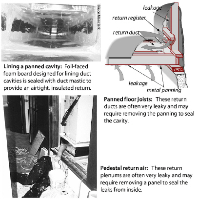
|
SWS Detail: 3.1602.1 Air Sealing Duct System, 3.1602.5 Return—Framed Platform, 3.1602.4 Air Sealing System Components, 3.1601.8 Preparation and Mechanical Fastening—Mid and High Rise, 3.1602.7 Return and Supply Plenums in Basements and Crawl Spaces, 3.1601.3 Support |
Inspect these places in the duct system and seal them as needed.
ü Plenum joint at air handler: Technicians might have had problems sealing these joints because of a lack of space. Seal these plenum connections thoroughly even if you must cut an access hole in the plenum. Use silicone caulking or foil tape instead of mastic and fabric mesh here for future access — furnace replacement, for example.
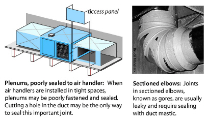
ü Joints at branch takeoffs: Seal these important joints with a thick layer of mastic. Fabric mesh tape should cover gaps and reinforce the seal at gaps.
ü Joints in sectioned elbows: Known as gores, these are usually leaky and require sealing with duct mastic.
ü Tabbed sleeves: Attach the sleeve to the main duct with 3-to-5 screws and apply mastic plentifully. Or better, remove the tabbed sleeve and replace it with a manufactured takeoff, which is easier to seal.
ü Flexduct-to-metal joints: Apply a 2-inch band of mastic to the end of the metal connector. Attach the flexduct’s inner liner with a plastic strap, tightening it with a strap tensioner. Attach the insulation and outer liner with another strap.
ü Damaged flex duct: Replace flex duct when it is punctured, deteriorated, or otherwise damaged.
ü Deteriorating ductboard facing: Replace ductboard, preferably with metal ducting, when the facing deteriorates because this deterioration leads to excessive air leakage.
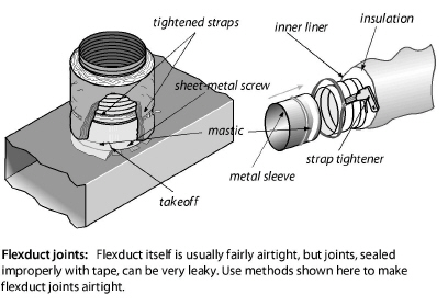
ü Consider closing supply and return registers in unoccupied basements or crawl spaces.
ü Seal the joint between the boot and the ceiling, wall, or floor between conditioned and unconditioned areas.
Duct Support
ü Support rigid ducts and duct joints with duct hangers at least every 5 feet or as necessary to prevent sagging of more than one-half inch.
ü Support duct board or flex duct every 4 feet using a minimum of 1 ½" wide support material.
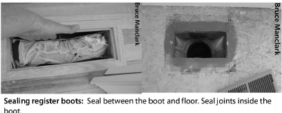
8.15.4 Materials for Duct Sealing
Duct mastic is the best duct-sealing material because of its superior durability and adhesion. Apply mastic at least 1/16-inch thick, and use reinforcing mesh for all joints wider than 1/8-inch or joints that may move. Install screws to prevent joint movement or separation.
Aluminum foil or cloth duct tape aren’t good materials for duct sealing because their adhesive often fails. Cover any tape with mastic extending 1" past the edges of the tape to prevent tape’s adhesive from drying out and failing. Any tape that is used as part of an assembly it should be UL 181 rated
|
SWS Detail: 4.1601.1 Insulating Flex Ducts, 4.1601.2 Insulating Metal Ducts |
Insulate supply ducts that are installed in unconditioned areas outside the thermal boundary such as crawl spaces, attics, and attached garages with vinyl- or foil-faced duct insulation. Don’t insulate ducts that run through conditioned areas unless they cause overheating in winter or condensation in summer. Use these best practices for installing insulation.
ü Always perform necessary duct sealing before insulating ducts.
ü Duct-insulation R-value must be ≥R-8.
ü It is not cost-effective to remove existing R-4 flex ducts and replace them with R-8. If possible, cover with insulation, if added, as appropriate.
ü Insulation should cover all exposed supply ducts, with no significant areas of bare duct left uninsulated.
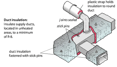
ü Insulation’s compressed thickness must be more than 75% of its uncompressed thickness. Don’t compress duct insulation excessively at corner bends.
ü Fasten insulation using mechanical means such as stick pins, twine, staples, or plastic straps.
ü Cover the insulation’s joints with tape to stop air convection.
ü Install the duct insulation 3 inches away from heat-producing devices such as recessed light fixtures.
Caution: Burying ducts in attic insulation is common in some regions and it reduces energy losses from ducts. However, condensation on ducts in humid climates is common during the air-conditioning season, so don’t allow cellulose to touch metal ducts to avoid corrosion from cellulose’s ammonium sulfate fire retardant.
Important Note: Tape can be effective for covering joints in the insulation to prevent air convection, but the tape fails when expected to resist the force of the insulation’s compression or weight. Outward-clinch staples or plastic straps can help hold the insulation facing and tape together.
8.16.1 Spray Foam Duct Insulation
|
SWS Details: 3.1602.2 Duct Spray Polyurethane Foam (SPF) Installation |
High-density spray foam insulation is also a good duct-insulation option, assuming it is listed as ASTM E-84 or UL 723. Spray foam is particularly helpful in areas where the foam can seal seams and insulate in one application. However, the spray foam application is limited by space around the duct to a greater degree than wrapping with fiberglass blankets.
8.17 Hot-Water Space-Heating Distribution
The most significant energy wasters in hot-water systems are poor steady-state efficiency, off-cycle flue losses stealing heat from the stored water, and boilers operating at a too-high water temperature. For information about boiler installation, see page 282.
8.17.1 Boiler Efficiency and Maintenance
|
SWS Details: 5.3104.2 Maintenance: Gas Boiler Service Inspection, 2.0203.3 Combustion Air—Boilers |
Monitor boiler performance and efficiency by inspecting for these problems.
• Corrosion, scaling, and dirt on the water side of the heat exchanger.
• Corrosion, dust, and dirt on the fire side of the heat exchanger.
• Excess air during combustion from air leaks and incorrect fuel-air mixture.
• Off-cycle air circulation through the firebox and heat exchanger, removing heat from stored water.
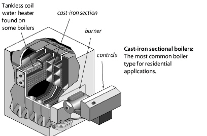
Boiler Efficiency Improvements
Consider the following maintenance and efficiency improvements for both hot-water and steam boilers based on boiler inspection.
ü Check for leaks on the boiler, around its fittings, or on any of the distribution piping connected to the boiler.
ü Clean fire side of heat exchanger of noticeable dirt.
ü Drain water from the boiler drain until the water flows clean. Then add water to refill the system.
8.17.2 Hydronic Distribution System Improvements
|
SWS Details: 5.3101.2 Space Load Calculation—Heat Emitter Sizing, 5.3104.2 Maintenance: Gas Boiler Service Inspection, 5.3104.1 Controls—Thermostat Replacement, 5.3104.4 Optimize Outdoor Reset Boiler Controller (Hot Water), 5.3104.5 Optimize Outdoor Reset Valve Controller (Hot Water), 5.3104.6 Repair/Replace Existing Thermostatically Controlled Zone Valves (Hot Water) |
Hydronic distribution systems consist of the supply and return piping, the circulator, expansion tank, air separator, air vents, and heat emitters. A properly designed and installed hydronic distribution system can operate for decades without service. However, many systems have installation flaws or need service.
Note: You can recognize a hot-water boiler by its expansion tank, located somewhere above the boiler. The expansion tank provides an air cushion to allow the system’s water to expand and contract as it is heated and cooled. Without a functioning expansion tank excessive pressure in the boiler discharges water through the pressure-relief valve.
Safety Checks and Improvements
Work with contractors and technicians to specify and verify the following safety and efficiency tests and inspections.
ü Verify the existence of a 30-psi-rated pressure relief valve. The pressure relief valve should have a drain pipe that terminates 6 inches from the floor. Replace a malfunctioning valve, or install a pressure relief valve if none exists. Look for signs of leakage or discharges from that valve. Find out why the pressure relief valve is discharging.
ü Verify that the expansion tank isn’t waterlogged or isn’t too small for the system. A waterlogged expansion tank can make the pressure relief valve discharge. Measure the expansion tank’s air pressure. A common pressure for one and two-story buildings is 12 psi. The pressure in taller buildings should be approximately one (1) psi per 2.3 feet of the distribution system’s height.
ü If you observe rust in venting, verify that the return water temperature is warmer than 130°F for gas and warmer than 140°F for oil. These minimum water temperatures prevent acidic condensation.
ü Verify that high-limit control disengages the burner at a water temperature of 200°F or less.
ü Lubricate circulator pump(s) if necessary.
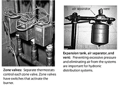
Simple Efficiency Improvements
Do the following energy-efficiency improvements.
ü Repair water leaks in the system.
ü Remove corrosion, dust, and dirt on the fire side of the heat exchanger.
ü Check for excess air during combustion from air leaks and incorrect fuel-air mixture. See “Critical Combustion-Testing Parameters” on page 274.
ü Bleed air from radiators and piping through air vents on piping or radiators. Most systems fill automatically through a shutoff and pressure-reducing valve connected to the building’s water supply. If there is a shutoff and no pressure-reducing valve, install one and set it to the hydronic-system pressure. Then check the system pressure at the expansion tank, and adjust the pressure as necessary.
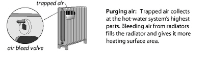
ü Vacuum and clean fins of fin-tube convectors if you notice dust and dirt there.
ü Insulate all supply and return piping, passing through unheated areas, with appropriate pipe insulation, at least one-inch thick, rated for temperatures up to 200° F.
Improvements to Boiler Controls
Consider these improvements to control systems for hot-water boilers.
ü Install outdoor reset controllers to regulate water temperature, depending on outdoor temperature.
ü If possible, operate the boiler without a low-limit control for maintaining a minimum boiler-water temperature. If the boiler heats domestic water in addition to space heating, the low-limit control may be necessary.
ü After control improvements like two-stage thermostats or reset controllers, verify that return water temperature is high enough to prevent condensation and corrosion in the chimney as noted previously.
ü Install electric vent dampers on natural-draft gas- and oil-fired high-mass boilers.
8.18 Steam Heating and Distribution
Steam heating is less efficient than hot-water heating because steam requires higher temperatures than hot water. For single-family homes, consider replacing a steam heating system with a hot-water or forced-air system. Multifamily buildings, especially multi-story buildings, may have little choice but to continue with steam because of the high cost of switching systems.
Note: You can recognize a steam boiler by its sight glass, which indicates the boiler’s water level. Notice that the water doesn’t completely fill the boiler, but instead allows a space for the steam to form above the boiler’s water level.
If the steam-heating system remains, operate it at the lowest steam pressure that heats the building adequately. Two psi on the boiler-pressure gauge is a practical limit for many systems although some systems can operate at pressures down to a few ounces per square inch of pressure. Traps and air vents are crucial to operating at a low steam pressure.
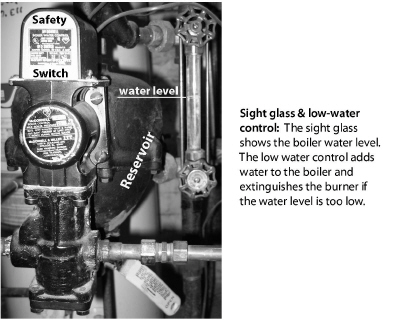
8.18.2 Steam System Maintenance
Do these safety and maintenance tasks on steam systems.
ü Verify that steam boilers have functioning high-pressure limits and low-water cut-off controls.
ü Verify the function of the low-water cutoff by flushing the low-water cutoff with the burner operating. Combustion should stop when the water level in the boiler drops below the level of the float. If combustion continues, repair or replace the low-water cutoff.
ü Verify that flush valves on low-water cutoffs are operable and don’t leak water.
ü Ask owner about instituting a schedule of blow-down and chemical-level checks.
ü Specify that technicians drain mud legs on return piping.
8.18.3 Steam System Energy Conservation
|
SWS Details: 5.3104.14 Tuneup and Upgrades 5.3104.3 Maintenance: Checklist, 5.3104.8 Boiler Water Treatment, 5.3104.9 Inspection Checklist, 5.3102.32 Install Thermostatic Radiator Valves |
Specify the following efficiency checks and improvements for steam systems.
Electric vent dampers reduce off-cycle losses for both gas- and oil-fired steam systems.
One-Pipe Steam
ü Verify that high-pressure limit control is set at or below 1 (one) psi or as low as acceptable in providing heat to the far ends of the building.
ü Verify that air vents function and that all steam radiators receive steam during every cycle. Air vents release air to make room for steam. Major pipe risers and all radiators should have vents.
ü Unplug air vents or replace malfunctioning vents as necessary. Add vents to steam lines and radiators as needed to get steam to all the registers.
ü Radiator air vents should be open to release air while the system is filling with steam, then closed when steam reaches the vents. Steam need not fill radiators on every cycle. In mild weather, steam partly fills radiators before the boiler cycles off.
ü Replace malfunctioning radiator air vents as necessary. However, don’t over-vent radiators because this can cause overheating and water hammer from too much steam condensing.
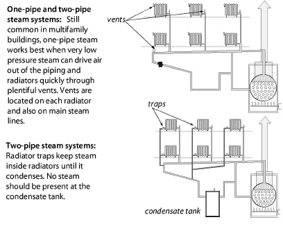
Two-Pipe Steam: General Improvements
ü Consider a modern high-efficiency power burner and electric vent damper as retrofits for steam boilers.
ü Clean fire side of heat exchanger of noticeable dirt.
ü Insulate all steam piping that passes through unconditioned areas to at least R-3 with fiberglass or specially designed foam pipe insulation rated for steam piping.
ü Consider installing remote sensing thermostats that vary cycle length according to outdoor temperature and include night-setback capability.
Two-Pipe Steam: Traps and Orifices
ü Inspect return lines and condensate receiver for steam coming back to the boiler, which is a sign of leaky traps. Check radiator and main line traps for steam leakage.
ü Check steam traps with a digital thermometer or listening device to detect any steam escaping from radiators through the condensate return. Replace leaking steam traps or their thermostatic elements.
ü When you can gain access to all the system’s steam traps, repair leaking steam traps or replace them. Replace all failed traps at the same time to prevent new traps failing because of water hammer from steam leakage through neighboring failed traps.
ü The only 100% reliable way to test a steam trap is to connect it to a test apparatus and see if it allows steam to pass. However if you have an accurate thermometer, the temperature on the radiator side of a functioning trap should be more than 215°F and the temperature on the return side of that trap should be less than 205°F when steam occupies the radiator.
ü When you can’t gain access to all the system’s steam traps at the same time, consider abandoning failed steam traps and installing radiator-inlet orifices in two-pipe steam radiators. The orifices limit steam flow to an amount that can condense within the radiator. Orifices can also reduce steam delivery to oversized radiators by 20% or a little more.
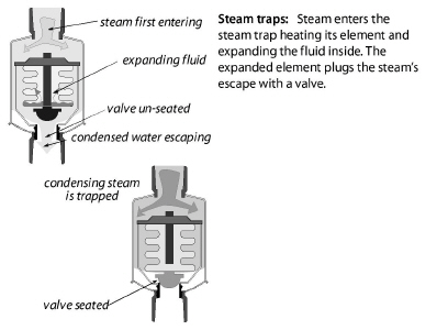
Two-Pipe Steam: Thermostatic Radiator Valves
Consider controlling radiators with thermostatic radiator valves (TRVs) except for radiators in the coolest rooms. TRVs can be used with systems equipped with either traps or orifices.
For effective temperature control, locate the thermostatic element of the TRVs in the path of cool air moving toward the radiator or convector. TRVs are available with sensors located remotely from the valve, which solves the problem of a valve located where the radiator heats a valve-mounted sensor, fooling it into closing.
8.18.4 Converting Steam Distribution to Hot Water
Quite a few steam systems have been converted to hot water distribution over the years by using the existing distribution piping, radiators, or both. Although some of these systems work well, many have problems. Converting steam to hot water has a number of potential problems, including the following.
• The conversion increases the operating pressure of the old pipes by a factor of 10 and this could cause leaks.
• In two-pipe systems, the return may not be large enough and require re-piping.
• In one-pipe steam the return must be installed to every radiator.
• The steam radiators may not be large enough to heat adequately with hot water.
• The existing radiators may be the type that won’t work with hot water.
For these reasons, it’s better to fix the steam system than to convert the system to hot water.
A programmable thermostat may be a big energy saver if the building’s occupants understand how to program it. However, a programmable thermostat won’t save any energy if occupants already control day and night temperatures effectively.
If you replace the existing thermostat, as a part of weatherization work, discuss programmable thermostats with occupants. If they can use a programmable thermostat effectively, then install one. Educate occupants on the use of the thermostat and leave a copy of manufacturer’s directions with them.
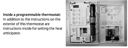
Many models of programmable thermostats have settings that you select from inside the thermostat. These settings include the heat-anticipator setting, which adjusts the cycle length of the heating or cooling system.
Important: Dispose of mercury-containing thermostats according to EPA guidance.
|
SWS Detail: 5.3003.4 Evaluating Electrical Service, 5.3003.26 Electrical Service—Mid and High Rise |
Electric heaters are usually 100% efficient at converting the electricity to heat in the room where they are located. However, electric heat is inherently inefficient because of the low efficiency of fossil-fuel electric power plants, which is why electricity is comparatively expensive as a heating option.
8.20.1 Electric Baseboard Heat
Electric baseboard heaters are zonal heaters controlled by thermostats within the zone they heat. Electric baseboard heat can help to minimize energy costs, if residents take advantage of the ability to heat by zones.
Baseboard heaters contain electric resistance heating elements encased in metal pipes. These are surrounded by aluminum fins to aid heat transfer. As air within the heater is heated, it rises into the room. This draws cooler air into the bottom of the heater.
ü Make sure that the baseboard heater sits at least an inch above the floor to facilitate good air convection.
ü Clean fins and remove dust and debris from around and under the baseboard heaters as often as necessary.
ü Avoid putting furniture directly against the heaters. To heat properly, there must be space for air convection.
The line-voltage thermostats used with baseboard heaters sometimes may not provide good comfort because they allow the room temperature to vary by 2°F or more. Newer, more accurate line-voltage thermostats are available with a positive-off feature that prevents unintentional heating during mild weather.
Programmable thermostats for electric resistance increase and reduce the temperature automatically.
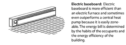
An electric furnace is usually the most expensive way to heat a building because electricity is relatively expensive and because of furnace duct losses.
Electric furnaces heat air moved by its fan over several electric-resistance heating elements. Electric furnaces have two to six elements — 3.5 to 7 kW each — that work like the elements in a toaster.
The 24-volt thermostat circuit energizes devices called sequencers that bring the 240 volt heating elements on in stages when the thermostat calls for heat. The multi-speed fan switches to higher speeds as more elements engage to keep the air temperature stable.
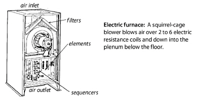
8.20.3 Central Heat-Pump Energy Efficiency
|
SWS Detail: 5.3003.4 Evaluating Electrical Service, 5.3003.26 Electrical Service—Mid and High Rise, 5.3002.12 Cooling Equipment—Installation, Maintenance, and Commissioning— Mid and High Rise |
Heat pumps move heat with refrigeration rather than converting it from the chemical energy of a fuel. An air-source heat pump is almost identical to an air conditioner, except for a reversing valve that allows refrigerant to follow two different paths, one for heating and one for cooling.
Like air conditioners, air-source heat pumps are available as centralized units with ducts or as room units. Heat pumps are 1.5 to 3 times more efficient than electric furnaces. Heat pumps can compete with combustion furnaces for comfort and value, but only with exemplary installation.
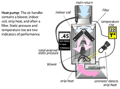
Heat pumps contain auxiliary electric resistance heating coils, known as strip heat. The energy efficiency of a heat pump depends on how much of the heating load the compressor provides compared to the strip heat.
Evaluating Heat Pumps During the Heating Season
Heat pumps should have two-stage thermostats designed for use with heat pumps. The first stage is compressor heating and the second stage is the inefficient strip heat.
Although we can generally evaluate the heat pumps refrigerant charge in the winter, it may be necessary to return in warm weather to more accurately charge the system. This summer verification is required with new heat-pump installations.
Consider these steps to evaluate conventional single-stage heat pumps during the winter.
ü Measure the airflow of the air handler by temperature rise method, flow plate, or flow hood. Heat pumps must have 400 cfm +/- 10% per ton.
ü With only the heat pump operating and the supplemental heat off, look for a temperature rise of approximately 20°F when the outdoor temperature is 32°F. Add or remove 1° of temperature rise for every 3° that the outdoor temperature is over or under 32°F.
ü Check for strip-heat operation by measuring amperage. Then use the chart shown here to find out if strip heat is operating.
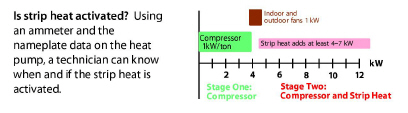
ü External static pressure should be 0.5 IWC (125 pascals) or less for older, fixed-speed blowers and less than 0.8 IWC (200 pascals) for variable-speed blowers. Lower external static pressure promotes higher airflow.
ü Seal supply and return ducts and insulate them after you’ve verified the airflow as adequate. Measure airflow again after duct sealing if the ducts were very leaky.
Most residential central heat pumps are split systems with the indoor coil and air handler indoors and outdoor coil and compressor outdoors. Individual room heat pumps are more efficient since they don’t have ducts, and are factory-charged with refrigerant.
In the summer, use the same procedures to evaluate central heat pumps as to evaluate central air conditioners, described on page 377.
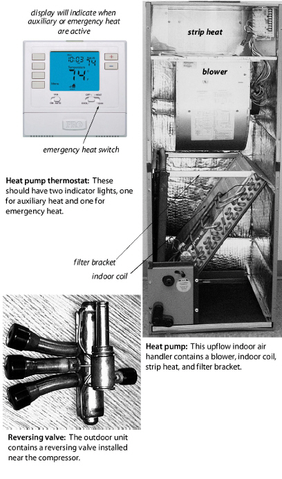
The illustration shows features of an energy-efficient heat pump installation.
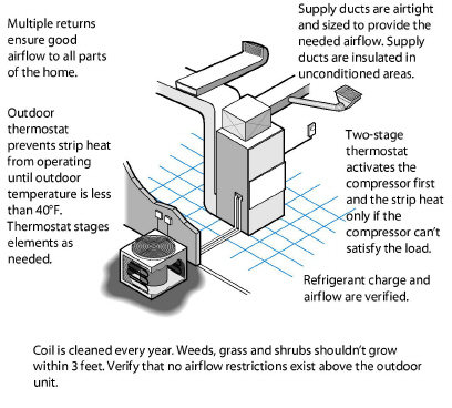
|
SWS Detail: 5.3003.4 Evaluating Electrical Service, 5.3302.1 Through-Wall and Room Air Conditioning Unit Replacement, 5.3003.26 Electrical Service—Mid and High Rise |
Room heat pumps can provide all or part of the heating and cooling needs for small homes and apartments. These one-piece room systems (also known as terminal systems) look like a room air conditioner, but provide heating as well as cooling. They can also provide ventilation air when the space requires neither heating nor cooling. They mount in a window or through a framed opening in a wall.
Room (or unitary) heat pumps can be a good choice for replacing existing unvented gas space heaters. Their fuel costs are somewhat higher than gas space heaters, but they are safer than combustion appliances.
Room heat pumps have an efficiency over central furnaces or central boilers because they heat a single zone and don’t have the delivery losses. If room heat pumps replace electric resistance heat, they consume only one-half to one-third the electricity to produce the same amount of heat.
Room heat pumps draw a substantial electrical load, and may require 240-volt wiring. Provide a dedicated electric circuit that can supply the equipment’s rated electrical input. Insufficient wiring capacity can result in dangerous overheating, tripped circuit breakers, blown fuses, or motor-damaging voltage drops. In most cases, a licensed electrician should confirm that the house wiring is sufficient. Don’t operate room heat pumps with extension cords or plug adapters.
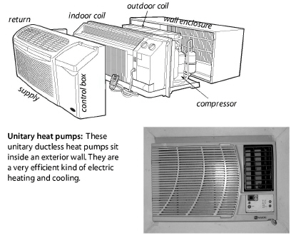
8.20.5 Ductless Minisplit Heat Pumps
|
SWS Detail: 5.3003.4 Evaluating Electrical Service, 5.3003.26 Electrical Service—Mid and High Rise |
Ductless minisplit heat pumps contain an outdoor condenser and one or more indoor fan-coil units that heat or cool the rooms. Mini-split heat pumps are among the most efficient heating and cooling systems available, providing 2-to-4 watt hours of heating or cooling for each watt hour of electricity they consume.
Ducted mini-splits have become popular for retrofitting multifamily buildings. Variable refrigerant flow (VRF) systems employ a computerized valving unit to distribute the correct amount of refrigerant to each terminal unit or head in large buildings.
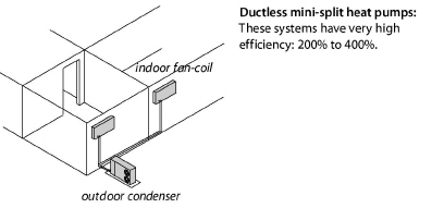
Consider minisplits heat pumps or VRF systems as replacement HVAC solutions when they are appropriate, for example.
• Buildings currently having no ducts.
• Buildings with poorly designed or deteriorating ducts outside the thermal boundary or located in areas, such as floor cavities and on roofs.
• Isolated parts of building such as additions or previously unconditioned areas.
• Very well-insulated, airtight, and shaded buildings.
• Rooms needing cooling in buildings with no central air conditioning.
• Masonry buildings, often multifamily, being retrofitted to replace obsolete central space-conditioning systems, for example: steam or obsolete packaged systems.
8.21 Evaluating Ducted Central Air-Conditioning Systems
|
SWS Detail: 5.3003.4 Evaluating Electrical Service, 5.3003.26 Electrical Service—Mid and High Rise |
An energy-efficient home shouldn’t need more than a ton of air-conditioning capacity for every 1000 square feet of floor space. Window shading, attic insulation, and air leakage should be evaluated together with air-conditioner performance to size an air conditioner.
The following four installation-related problems are characteristic of central air conditioning systems.
1. Inadequate airflow
2. Duct air leakage
3. Incorrect charge
4. Oversizing
Refrigerant-charge testing and adjustment come after duct testing and sealing, which comes after airflow measurement and improvement.
The recommended airflow rate for central air-conditioning systems is between 350 CFM and 450 CFM per ton of refrigeration capacity. Heat pump airflow rate should be between 400 CFM and 450 CFM per ton.
|
Installation-Related Problem |
%B |
Savings Potential |
|---|---|---|
|
Duct air leakage (avg. 270 CFM25)C |
70% |
17% avg. |
|
Inadequate airflow |
70% |
7% avg. |
|
Incorrect charge |
74% |
12% avg. |
|
Oversized by 50% or more |
47% |
2–10% |
|
AReport sponsored by Environmental Protection Agency (EPA) and compiled from research from Multiple Field Studies BPercent of tested homes found with a significant problem. CThe number of homes of the duct-leakage studies was around 14,000; the number for the other problems was over 400 each. |
8.21.1 Central A/C-Heat Pump Inspection and Maintenance
|
SWS Detail: 5.3003.7 Occupant Education, 2.0702.2 Occupant Education, 2.0702.3 Building Operations Staff Education |
Air conditioners move a lot of air, and that air contains dust. The filter in the air handler catches most large dust particles. However some dust travels around or through the filter, depending on the filter and its mounting assembly. The condenser coil outdoors isn’t protected by a filter and is usually quite dirty.
Dirt enters the coil from the outside. The goal of this procedure is to drive the dirt out by spraying inside to outside. With high-pressure water, however, you can drive the dirt through the coil and into the cabinet where it drains out through drain holes.
ü Inspect the condenser coil and know that it is probably dirty even if it looks clean on the outside. Take a flat toothpick and scrape between the fins. Can you scrape dirt out from between the fins?
ü Use a stiff-bristle brush to remove visible surface from the outside of the condenser coil.
ü Apply a biodegradable coil cleaner to the outside of the coil. Then spray cold water through the coil, preferably from inside the cabinet. Many coils can tolerate a high-pressure spray but others need low-pressure spray to avoid bending the fins.
ü Straighten bent fins with a fin comb.
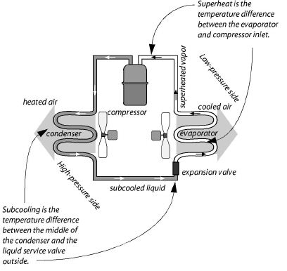
Cleaning the Evaporator Coil
Dirt enters the filter, blower, and coil from the return plenum.
ü Inspect the filter slot in the air handler or the filter grille in the return air registers. Do the filters completely fill their opening? Are the filters dirty?
ü Inspect the blower in the air handler after disconnecting power to the unit. Can you remove significant dirt from one of the blower blades with your finger? If the blower is dirty, then the evaporator coil is also dirty.
ü Clean the blower and evaporator. Rake surface dirt and dust off the coil with a brush. Then use an indoor coil cleaner and water to clean between the fins.
ü Straighten bent fins with a fin comb.
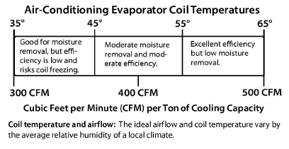
Calculate the correct size of an air conditioner before purchasing or installing it. The number of square feet of floor space that can be cooled by one ton of refrigeration capacity is determined by the home’s energy efficiency. Air-conditioners provide cooling most cost-effectively when they are sized accurately and run for long cycles.
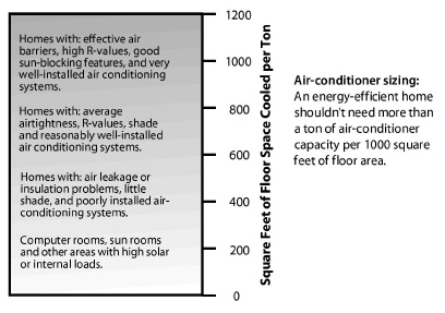
The cooling-cost reduction strategy should focus on making the home more energy efficient and making the air conditioner work more efficiently. Making the home more efficient involves shading, insulation, and air-leakage reduction. Making the air conditioner more efficient involves duct sealing, duct insulation, and a quality installation.
8.21.3 Duct Leakage and System Airflow
Unfortunately, duct leakage and poor airflow afflict most air-conditioning systems. The testing and mitigation of these problems was covered earlier in this chapter.
1. See “Air Filter Effectiveness” on page 339.
2. See “Ducted Air Distribution” on page 322.
8.21.4 Evaluating Air-Conditioner Charge
|
SWS Detail: 5.3003.23 Refrigerant Charge Evaluation—Low Rise, 5.3003.13 Refrigerant Charge Evaluation, 2.0302.1 Locking Refrigerant Caps—Mid and High Rise, 5.3003.5 Refrigerant Line Inspection |
Air-conditioning replacement or service includes refrigerant charge-checking. HVAC technicians evaluate refrigerant charge by two methods depending on what type of expansion valve the air conditioner has.
1. If the expansion valve has a fixed orifice, the technician performs a superheat test.
2. If the valve is a thermostatic expansion valve (TXV), the technician performs a subcooling test.
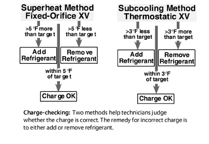
These two tests indicate whether the amount of refrigerant in the system is correct, or whether there is too much or too little refrigerant. The amount of refrigerant is directly related to the efficiency of the air-conditioning system.
Perform charge-checking after the airflow tests, airflow adjustments, and duct-sealing are complete. Do charge-checking during the cooling season while the air conditioner is operating.
Note: In multifamily buildings, install locking refrigerant caps on refrigerant access ports, if required by code, and as required by the SWS.